Name: Ian Van Horn Email: imvanhorn1@gmail.com
HW6
This homework introduce VGA
This homework uses Vivado
Task 1: Repeat example in
section 2.(20 points).
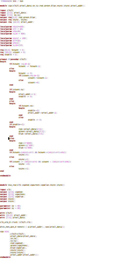
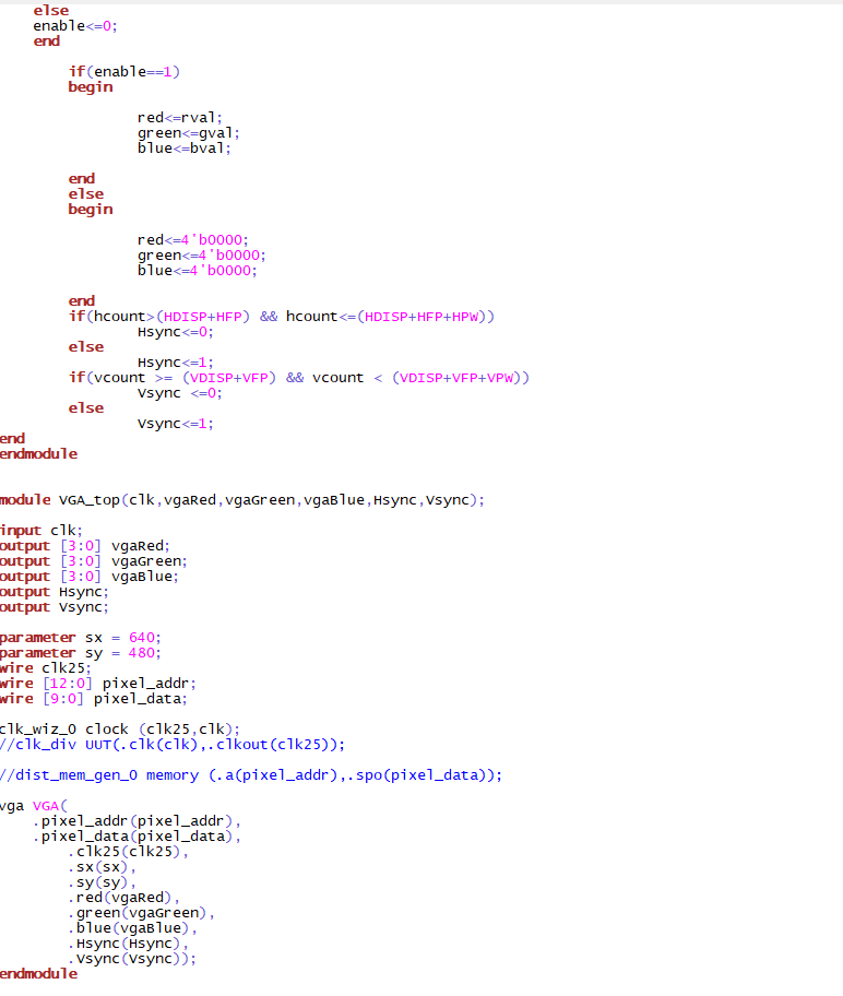
Figure 1-1: Code for VGA upload from website
The most complicated portion of the code is the timing and writing of
the pixels. Enable controls when pixels are in the desired display
area. Enable is set to 0 if Vcount is greater than sy. sy is the
desired size of the image vertically, if we are writing outside of this
range it makes sense enable is set to 0. When this happens the pixel
address is also set to -1 to move the area being written to. If the
verticle count is within the desired range the horizontal count is
checked. If that is in the desired range, enable is set to 1, if not it
is set to 0. The portion of the the code checking if H count and V
count are inbetween the values of HDISP+HFP+HPW and HDISP+HDP (for
verticle the corosponding verticle values) Is checking if the clock is
in the sync region between the front and back porch.
The module is very straightforward. The only nuance is because the
outclock is only changed on the rising edge of the 100MHZ clock it is
divided by 2x as much as expected. To divide the signal by 4, the out
clock is inverted every other rising edge of the clock. This is linked
in the testbench the same way as the clock wizard clock.
Video 2-1: Clock divider working
Task 3: White and Flashing
moniter(60 points).
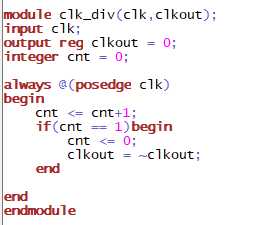
Figure 3-1:Updated Code to make screen white
Video 3-1: Demo of whitescreen
To make the moniter white, rather than reading from a image formated as
ROM, all pixels are just set to white, or RGB all 1111. These values
are assigned instead of the memory values. The size parameters in the
testbench are updated to fit the entire display.
Figure 3-2: Code to make moniter flash between red green and blue
Now the rgb values are assigned every 25 million clock cycles. The
clock is 25MHZ(after dividing) so the screen changes color every
second.
Video 3-2: Demo of flashing screen
Conclusion: The first use of VGA provided a lot of time consuming user errors. Once fixed all tasks were completed.