ENGR 433 - HW 5 2024 Spring
Name: Ian Van Horn
Email: imvanhorn1@gmail.com
HW 5
This homework introduces sequental circuts
This lab requires vivado
Task 1: Logic equations and
circut. (10 points).
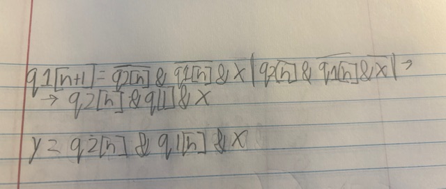
Figure 1-1: Logic equations
Logic expressions can be derived by looking at the high output states
on the truth table. The inputs are inverted if nessissary and anded
together. Each high state is or'ed with eachother.
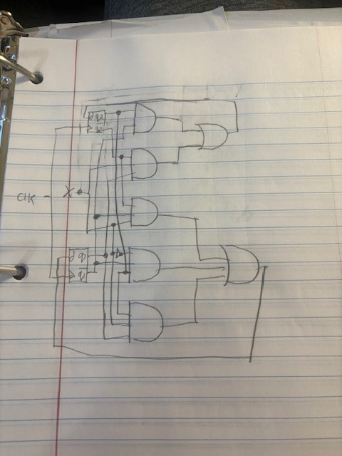
Figure 1-2: Circut Layout
The diagram can be drawn from the logical expressions by turning each
symbol into a gate. q[n+1] is the dff input and q[n] is the output.
Task 2: Section 3 work. (15 points).
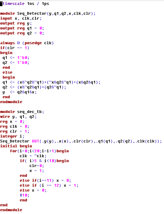
Figure 2-1: Code for sequence detector using logical expressions
The sequencer looks for a pattern in the current and next states of the
the inputs. The output (y) is high when the sequence is detected. In
this case the sequence is 1101.
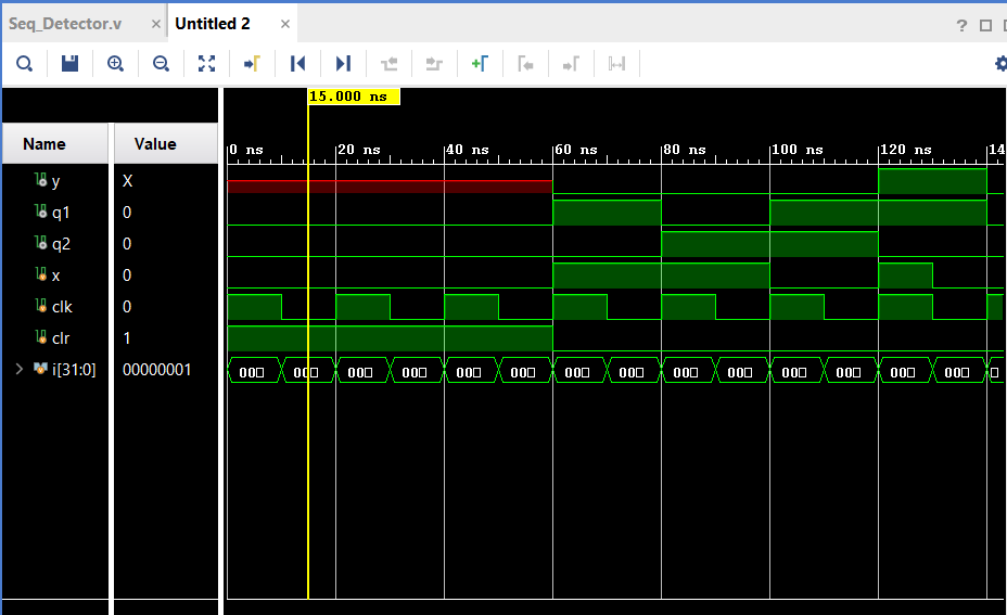
Figure 2-2: Simulation for code in Figure 2-1
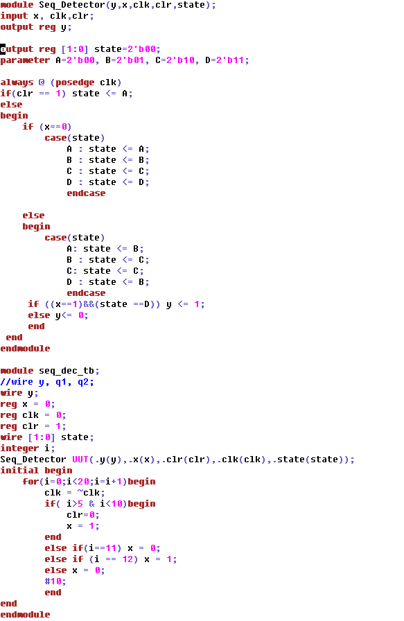
Figure 2-3: Behavioral modeling for sequence detector
This method uses more case statments in place of logical expressions.
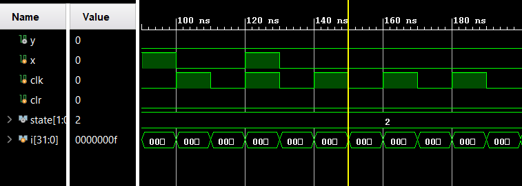
Figure 2-4: Simulation for Figure 2-3
Task 3: Sequence detector for 1011 (15 points).
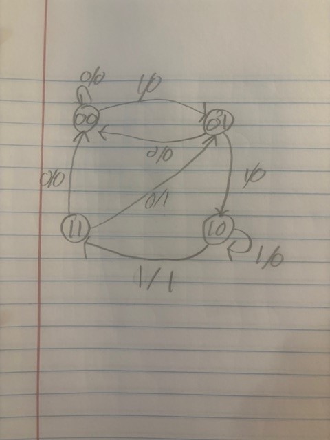
Figure 3-1: State diagram for modified decoder

Figure 3-2: Logical expressions and truth table for 1011 detector
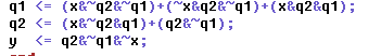
Figure 3-3: Portion of code updated from Figure 2-1
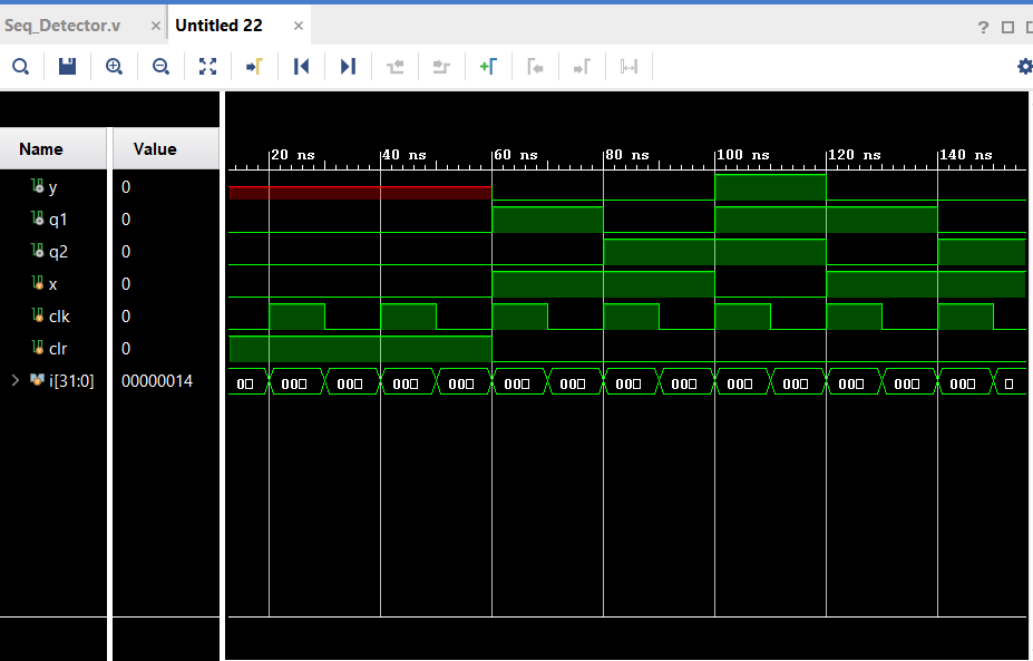
Figure 3-4: Simulation for 1011 sequence detector
When q2 is high and q1 is low (10) then q1 switches to high and q2 stays high (11) the 1011 sequence is detected and y is high
Task 4: Shift Regesters (20 points).

Figure 4-1: Siso code in gvim
This takes an input string of bits that is one bit wide and writes out
in the same shape. This is accomplished by writing the si (current
input bit) to the top of a set of registers and pushing the bits
current in the registers down. The bottom bit is so.
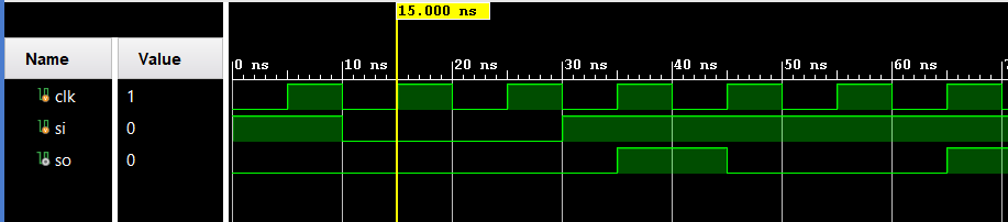
Figure 4-2: Siso simulation
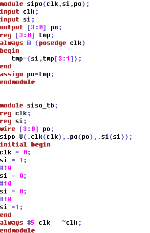
Figure 4-3: Sipo code in gvim
Now the serial input is written to a paralell output. This is done in a
similar fashon to siso but now the register stack is just assigned to
the output. This would be used to interface from an input wire to an IC.
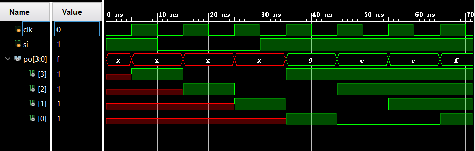
Figure 4-4: Sipo simulation
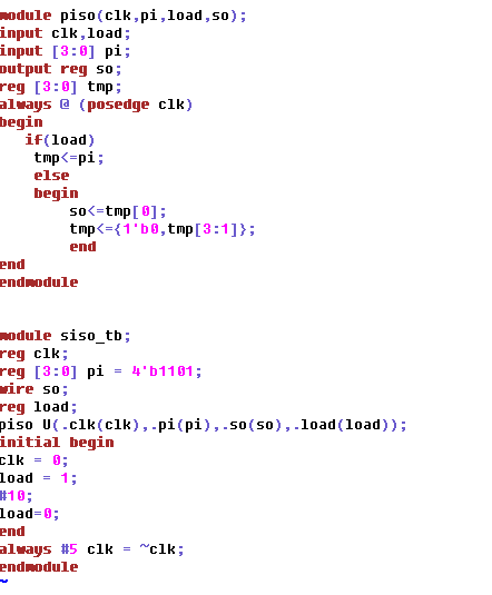
Figure 4-5: Piso code in gvim
Now a paralell input is sent as a serial output. One by one (bottom
first) bits in an array of registers are sent to so then set to 0 in
the rgister and pushed to the top. This would be used to write out of an IC to a pin.
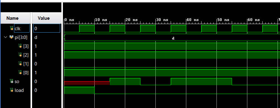
Figure 4-6: Piso simulation
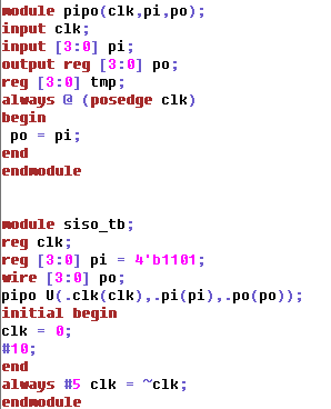
Figure 4-7: Pipo code in gvim
This the most simple regester. A parallell array of regesters is assigned to another array of registers.
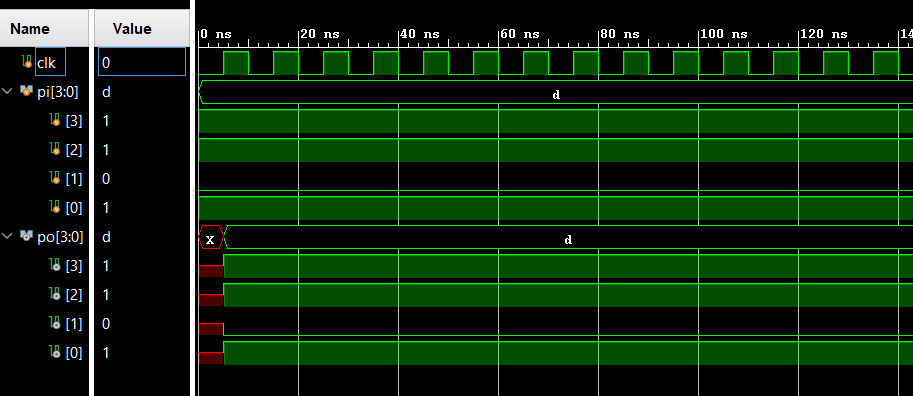
Figure 4-8: Pipo simulation
Task 5: Counter Module (20 points).
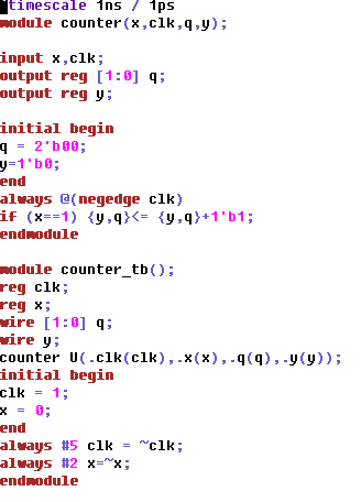
Figure 5-1: 2 bit up counter code in gvim
On the falling edge of a clk signal, if x is one add one to the count.
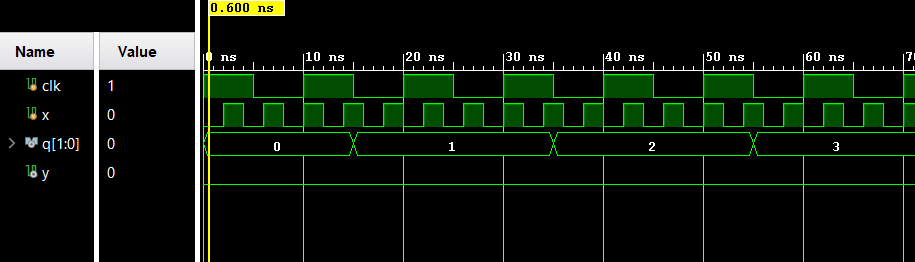
Figure 5-2: 2 bit up counter
Task 6: Custom circut (20 points).
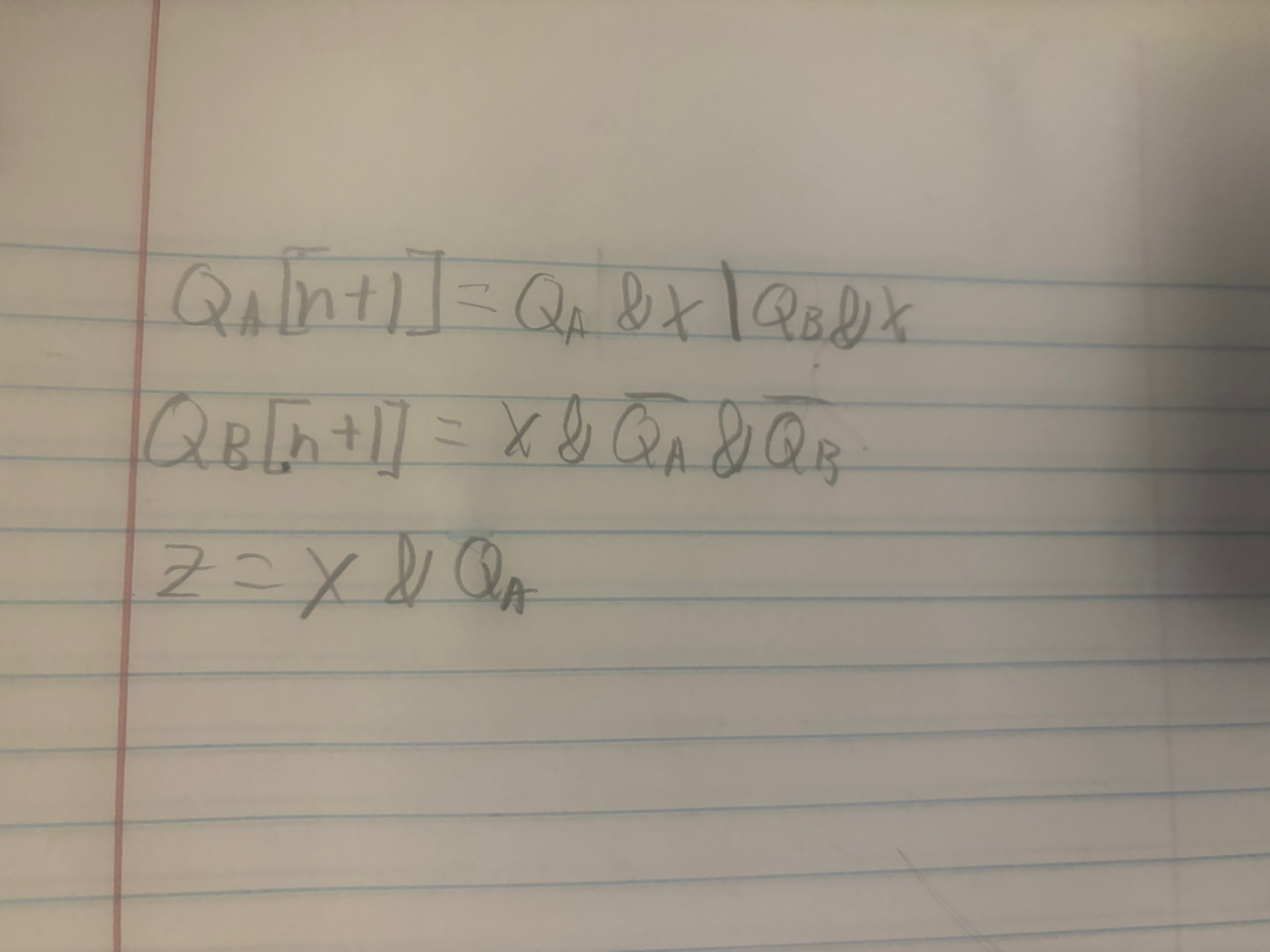
Figure 6-1: Logical expressions for circut derived form the circut diagram
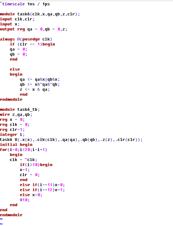
Figure 6-2: Gvim code for circut
The behavior of the crcut was modeled similarly to the sequencer in earlier parts, but with different logic
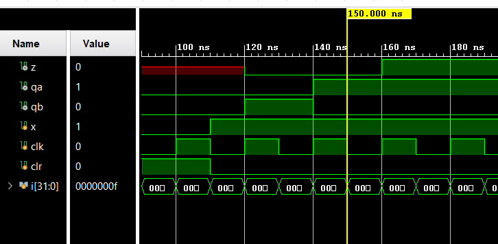
Figure 6-3: Simulation for circut