Name: Ian Van Horn Email: imvanhorn1@gmail.com
HW2 Data Types
This lab requires Vivado and Gvim
Task 1: Fixed and Floating
point (20 points).
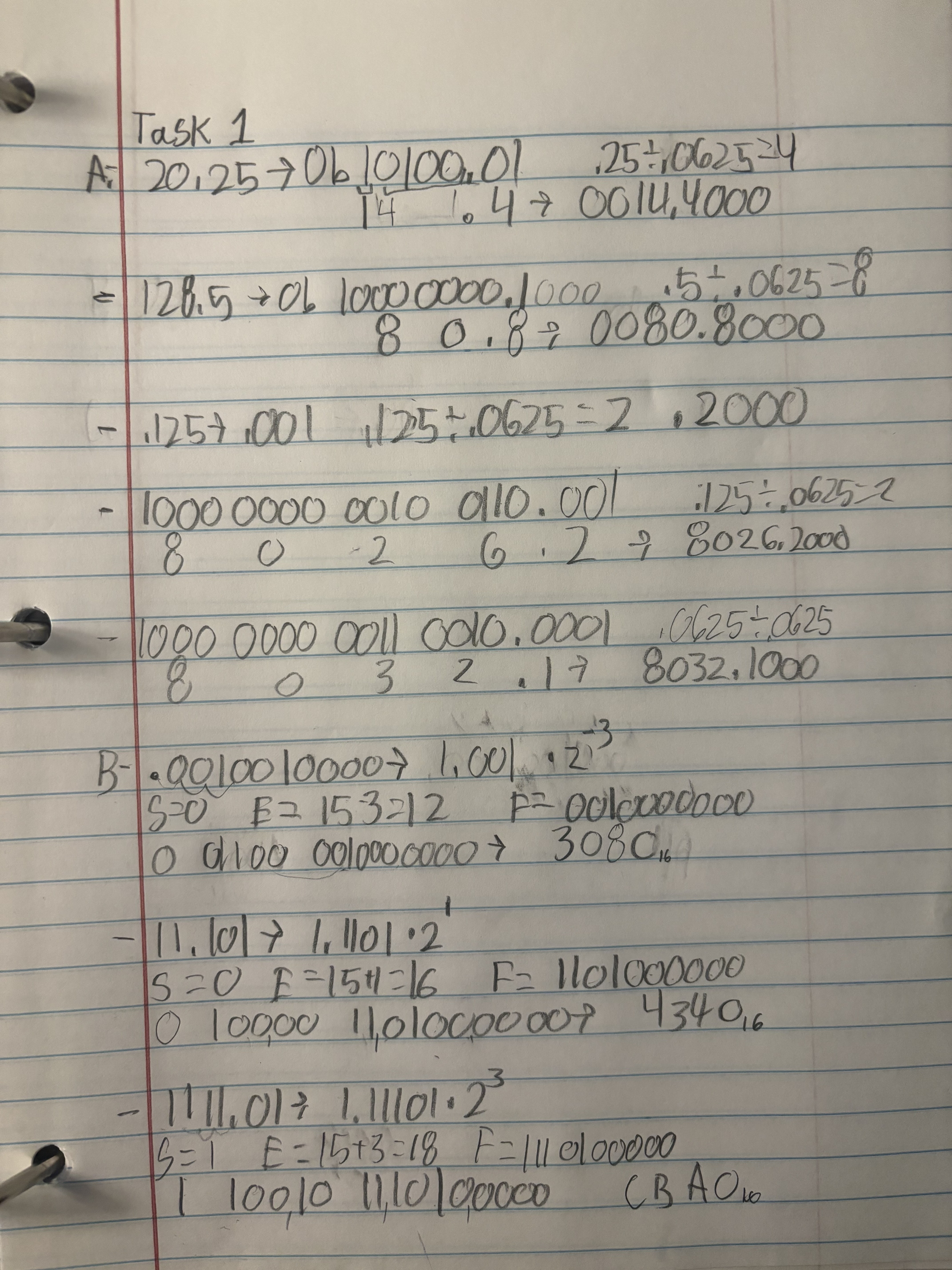
Figure 1.1: Hand Work
In part A, the first 3 calculations are unsigned. The first 2
calculations are limited to 16 bits on each side of the decimal. This
corrosponds to 4 hex digits. The 3rd calculation has 0 bits left of the
decimal and 16 to the right. The last 2 problems in part A are
signed. There are still 16 bits on each side of the decimal, but
the MSP represents sign so inly 15 bits left of the decimal represent
the absolute value of the number.
In part B all calculations are done in half precision. This means the
exponent bias is 15, one bit is used for S (sign), 5 bits are used for
E (exponent), 10 bits for F (number being raised to E). 16 Bits total
are used.
Task 2: Part 5 simulation (20
points).
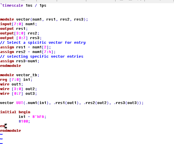
Figure 2.1: Gvim code for assigning values using hex
Num 1 is defined as an 8 bit vector. Res 1 is assigned as the 3rd bit
(3 from right) of in1. Res 2 is the MSB to the 5th bit of in one (5th
from right). res 3 then is assigned as num1 they are the same length so
the value is the same. It is worth noting the names of each bit in res
3 are indexed backwards of in1, but because this is just a name the
value held in each is the same. In the testbench, in one is defined
using hex (FA) but is still represented in binary.
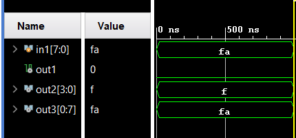
Figure 2.2: Simulation from code in Figure 2.1
In1 in binary is 1111 1010. out1, being the 3rd digit is 0. out2, being
the 4 MSBs is f (1111). in1 and out3 are the same length so they both
hold FA. Task 3: Section 7 Expearments
(30 points).
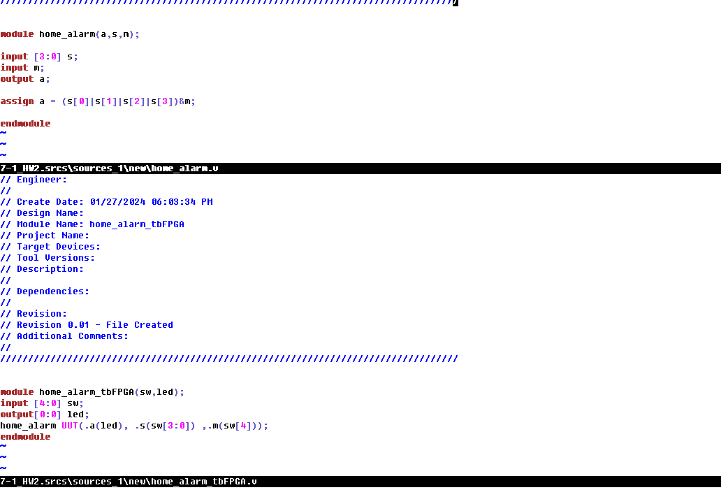
Figure 3.1: Gvim code for home security system
S is defined as a vector of length 4 as 4 switches are being used in
the "trigger" or gate. m is the on/off of the system. If any of the 4
switches are HIGH, a signal is passed so or logic is used. To continue
to pass this signal to an alarm, the system must be on so the signal is
anded with m. The output is a which is assigned to an led.
Video 3.1: Demonstration of home security system on FPGA
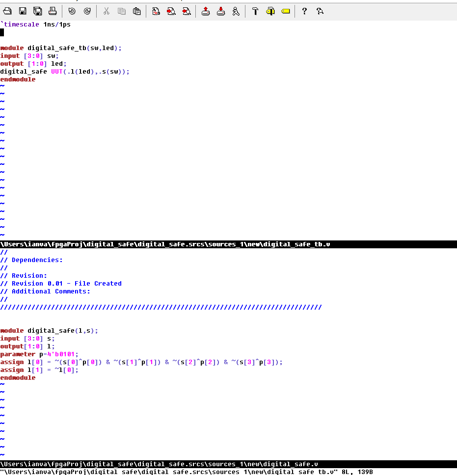
Figure: 3.2: Gvim code for digital safe
S is assigned to a vector of length 4 as 4 inputs from switches are
needed. A 'code' is set as a 4 digit binary number and saved as p. l
holds 2 vlaues in a vector, one to display when the save is locked
another when it is unlocked. Each switch has xor logic applied whith
the corrosponding bit in p. This means if the values are diffrent a 1
is returned. That value is inverted so when the numbers are the same a
1 is returned. Each signal from the switch and code logic is anded so
when all numbers match l[0] is high and l[1], being the inverse of l[0]
is low.
Video 3.2: Demonstration of vrtual safe
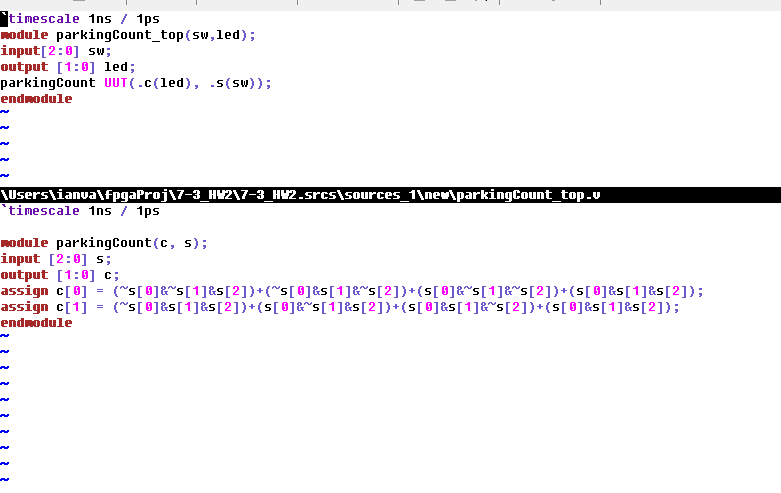
Figure 3.3: Gvim code for car counter
This code displayes the number of switches flipped as a binary number.
And logic and inverter logic are used such that any time 1 or 3
switches are flipped, a 1 is written to c[0] (the lsb). This is because
1 is 01 and 3 is 11, both of which have a 2 1 as the LSB. A one is
written to the MSB when all switches are on or 2 are on for the same
reason.
Video 3.3: Car counter demonstration
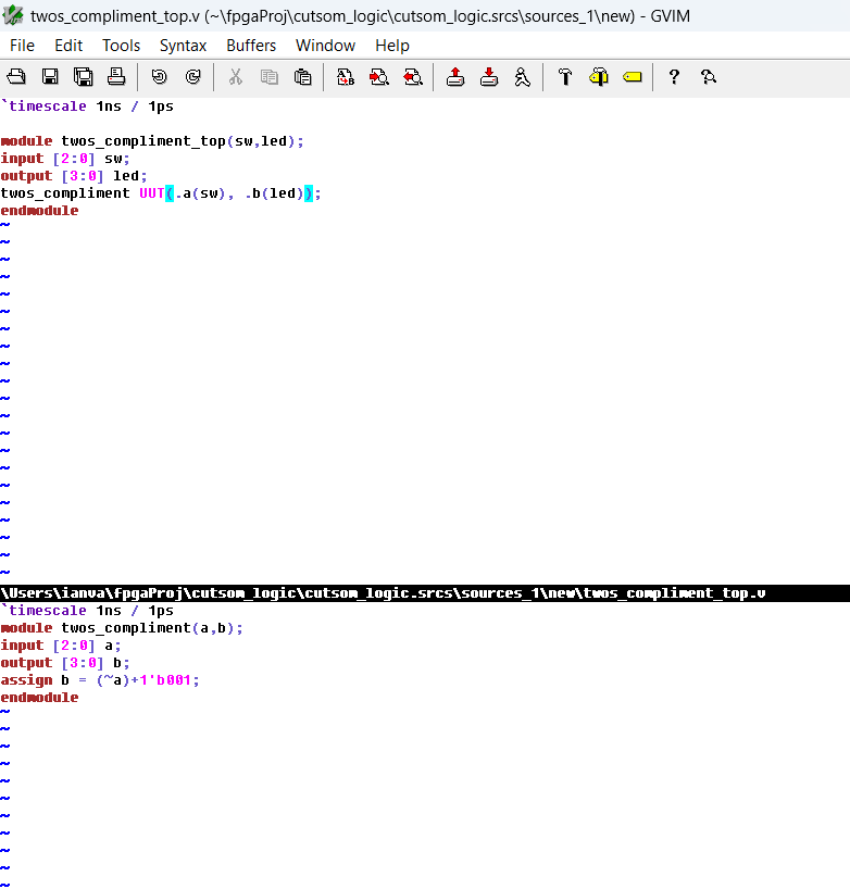
Task 4: Custom digital system -
2's Compliment(30 points).
This systen takes an input from the switches on the BASYS3 board and
interprets it as a binary number. That number is changed to it's 2's
compliment equivelient and displayed on the board's LEDs. 3 switches
are used to take a 3 bit input. 4 LEDs desplay the output, one extra to
prevent overflow. To change a number to two's compliment the number is inverted and 0b1 is added to it.
Figure 4.1: Gvim code for 2's compliment demonstration