ENGR 338 - Lab 8 2023 Fall
Name: Ian Van Horn
Email: imvanhorn1@gmail.com
Lab 8 MUX and High Speed FA
This lab covers the design and layout of a 8 bit multiplexer and a high speed 8 bit full adder
This lab requires the Eletric VLSI software
Task 1: Build an 8 bit MUX (20 points).
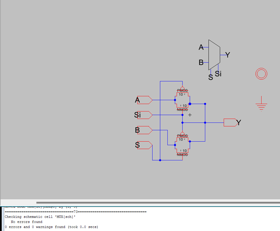
Figure 1: MUX schematic
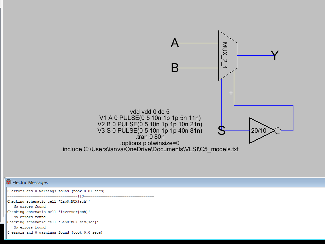
Figure 2: MUX Simulation Schematic
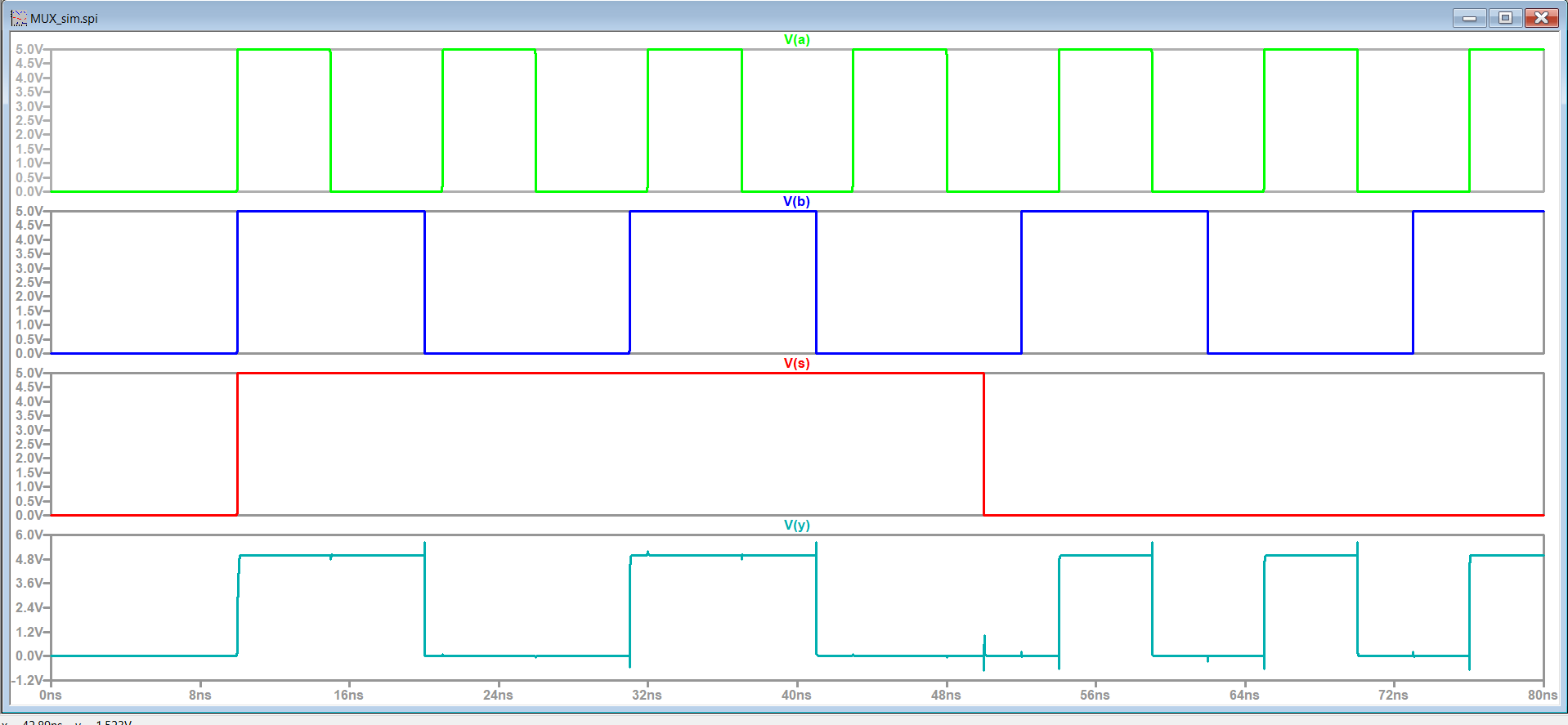
Figure 3: MUX Simulation Results
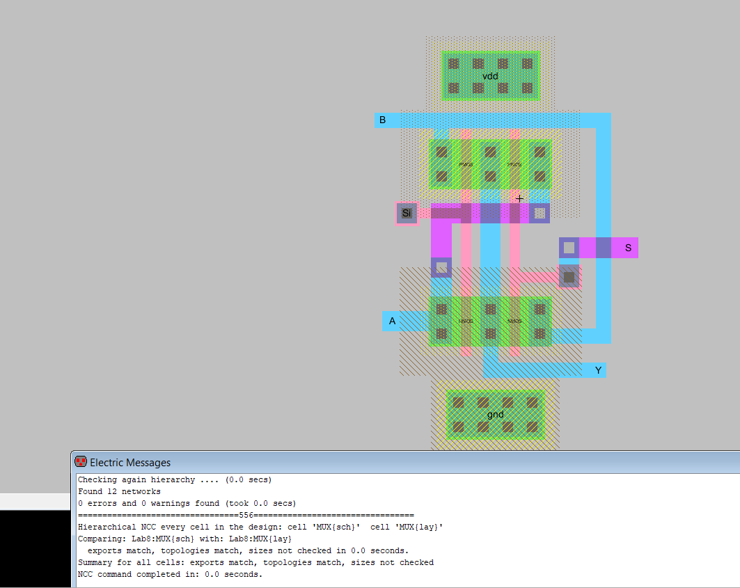
Figure 4: MUX layout
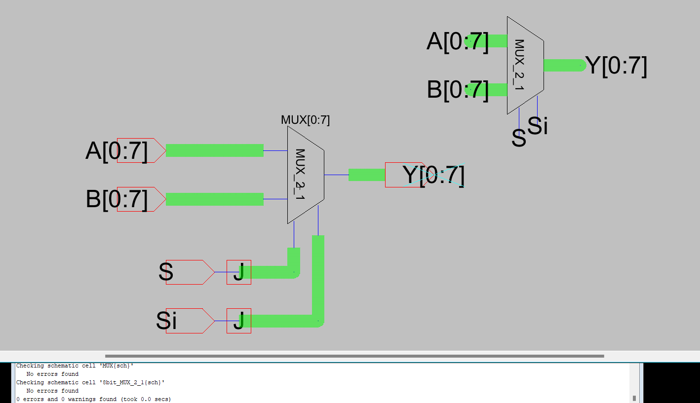
Figure 5: 8 Bit MUX Schematic
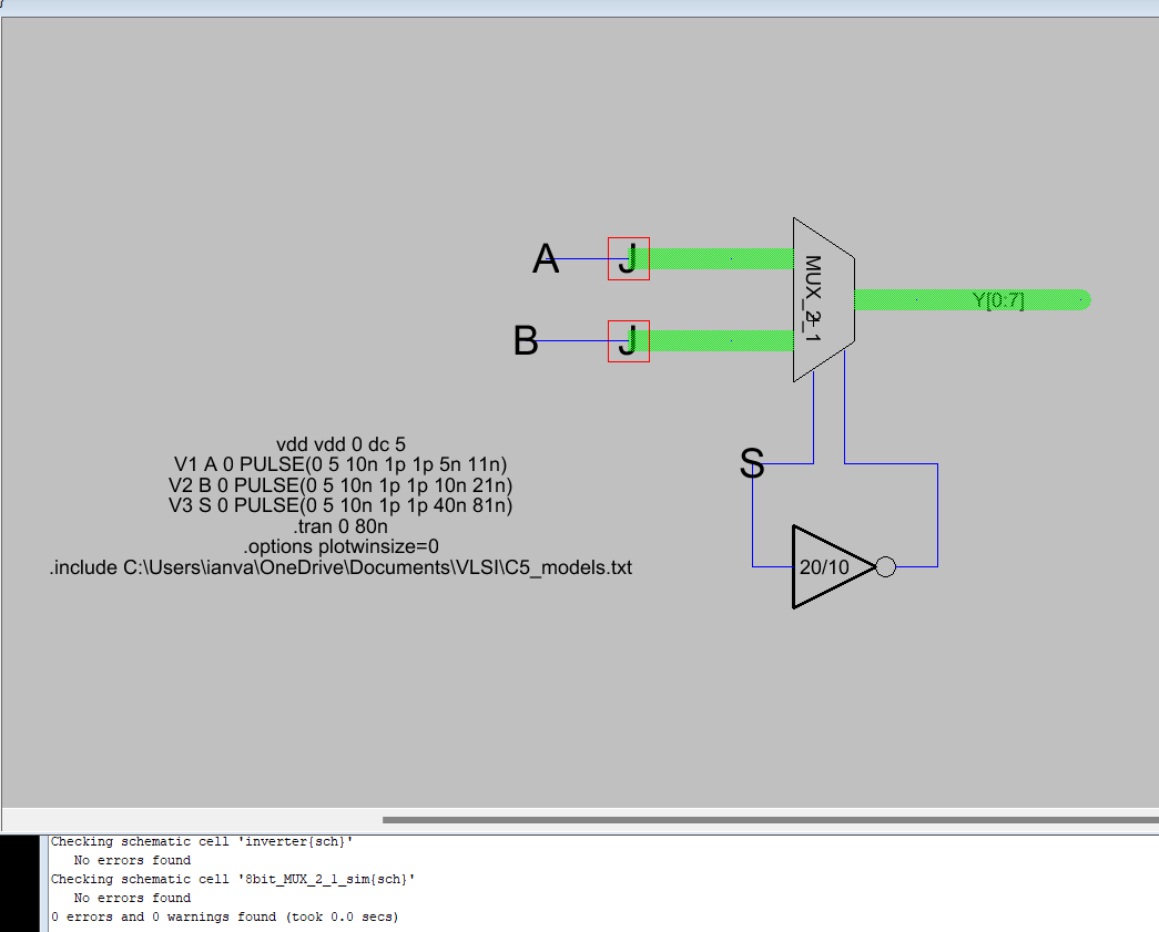
Figure 6: 8 Bit MUX Simulation Schematic
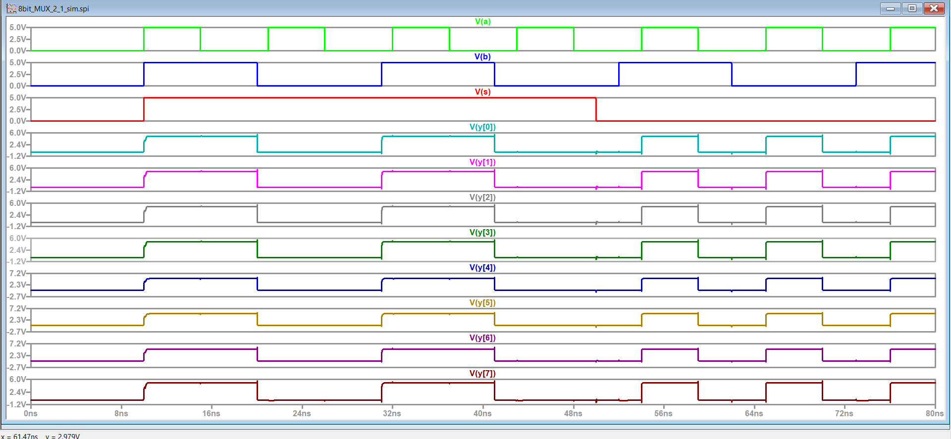
Figure 7: 8 Bit MUX simulation SPICE results
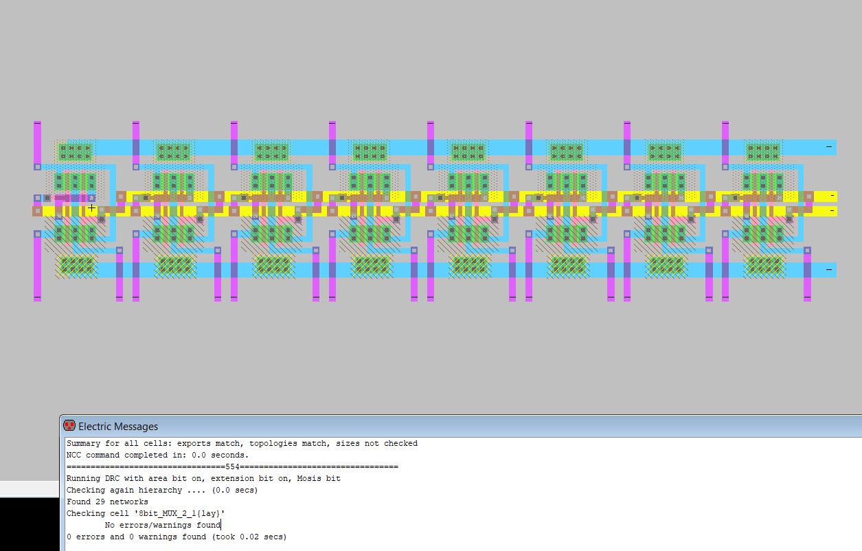
Figure 8: 8 Bit MUX Layout
Task 2: 1-Bit High Speed Full Adder. (40 points).
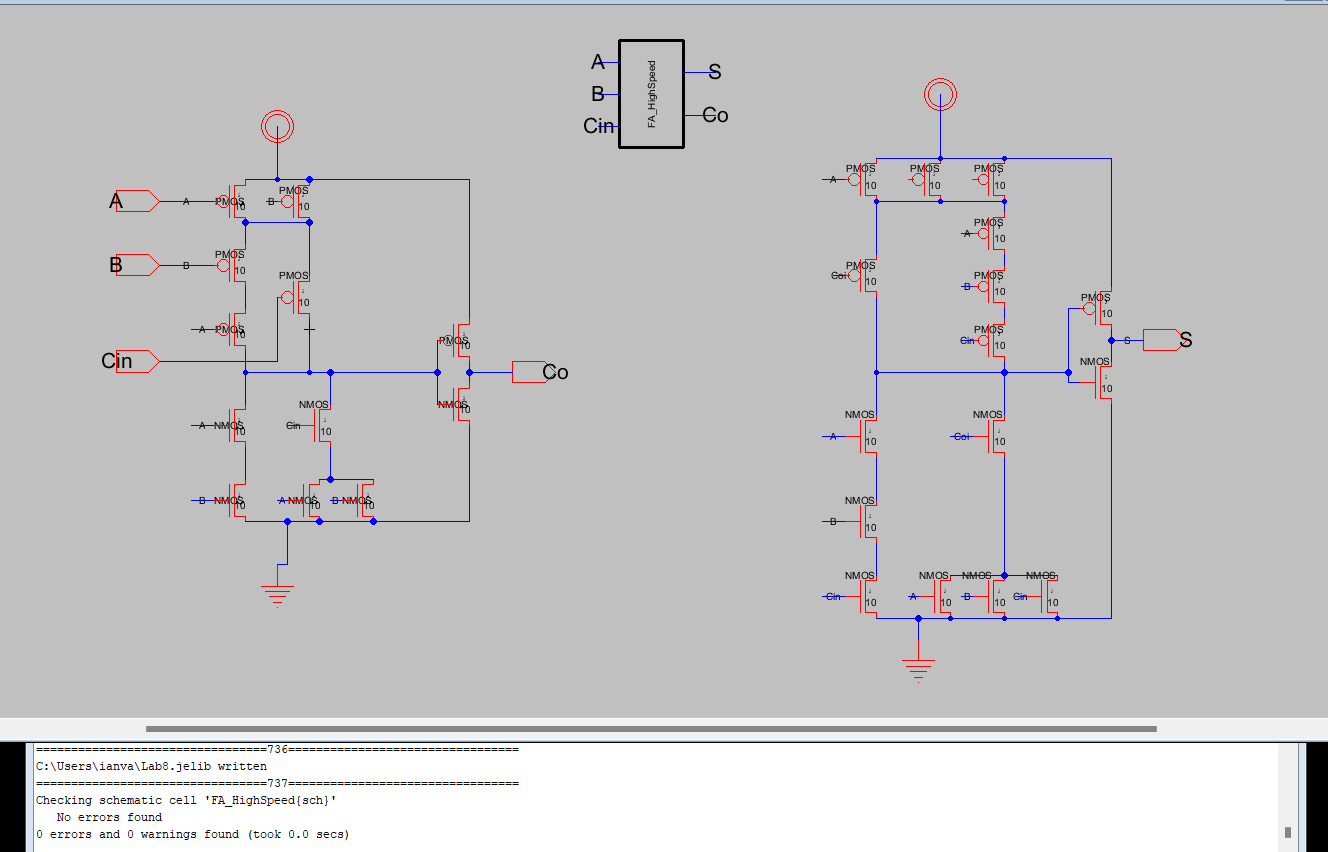
Figure 9: High Speed Full Adder Schematic
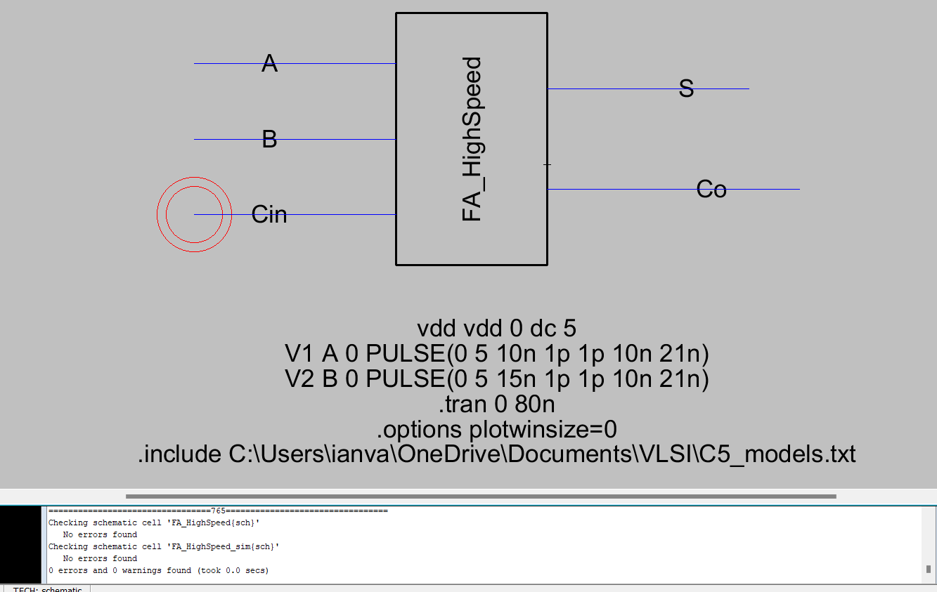
Figure 10: High Speed Full Adder Simulation Scheamtic
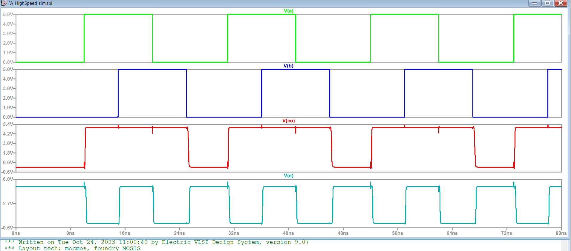
Figure 11: High Speed Full Adder Simulation SPICE Results
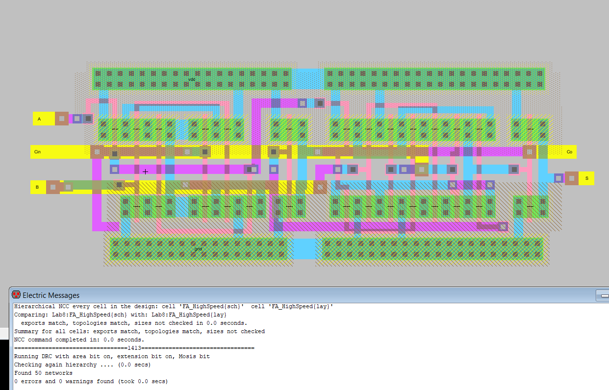
Figure 12: High Speed Full Adder Layout
Task 2: 8-Bit High Speed Full Adder. (30 points).
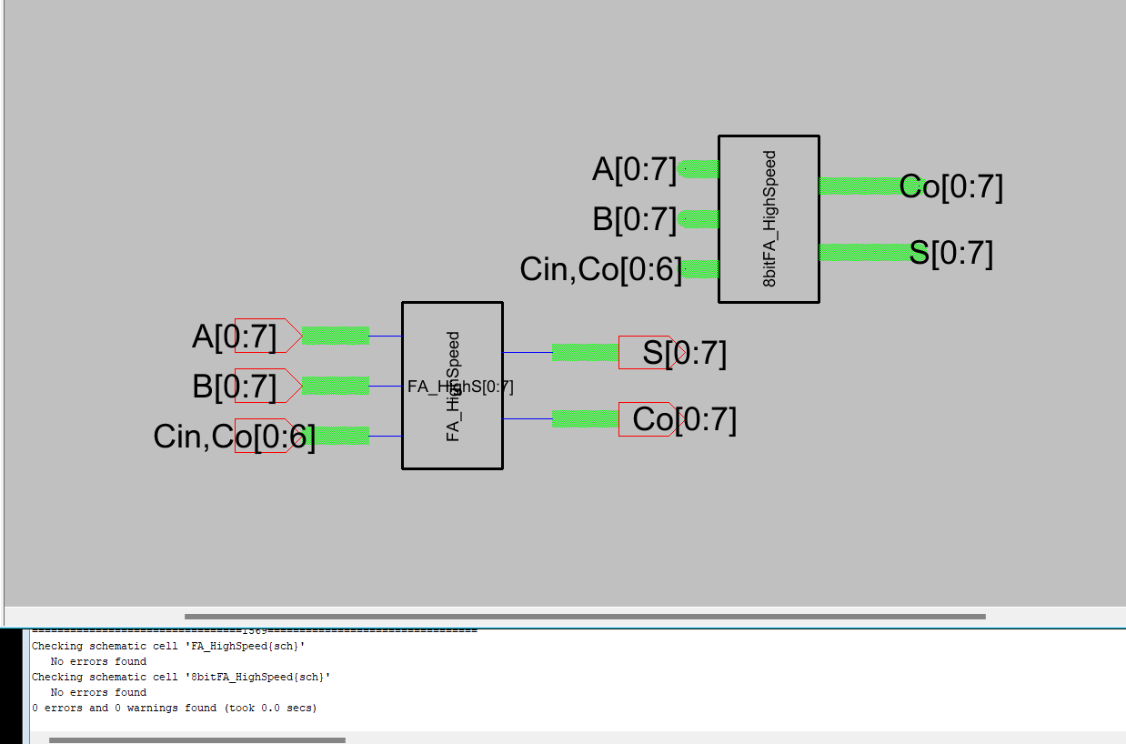
Figure 13: 8 Bit High Speed Full Adder Schematic
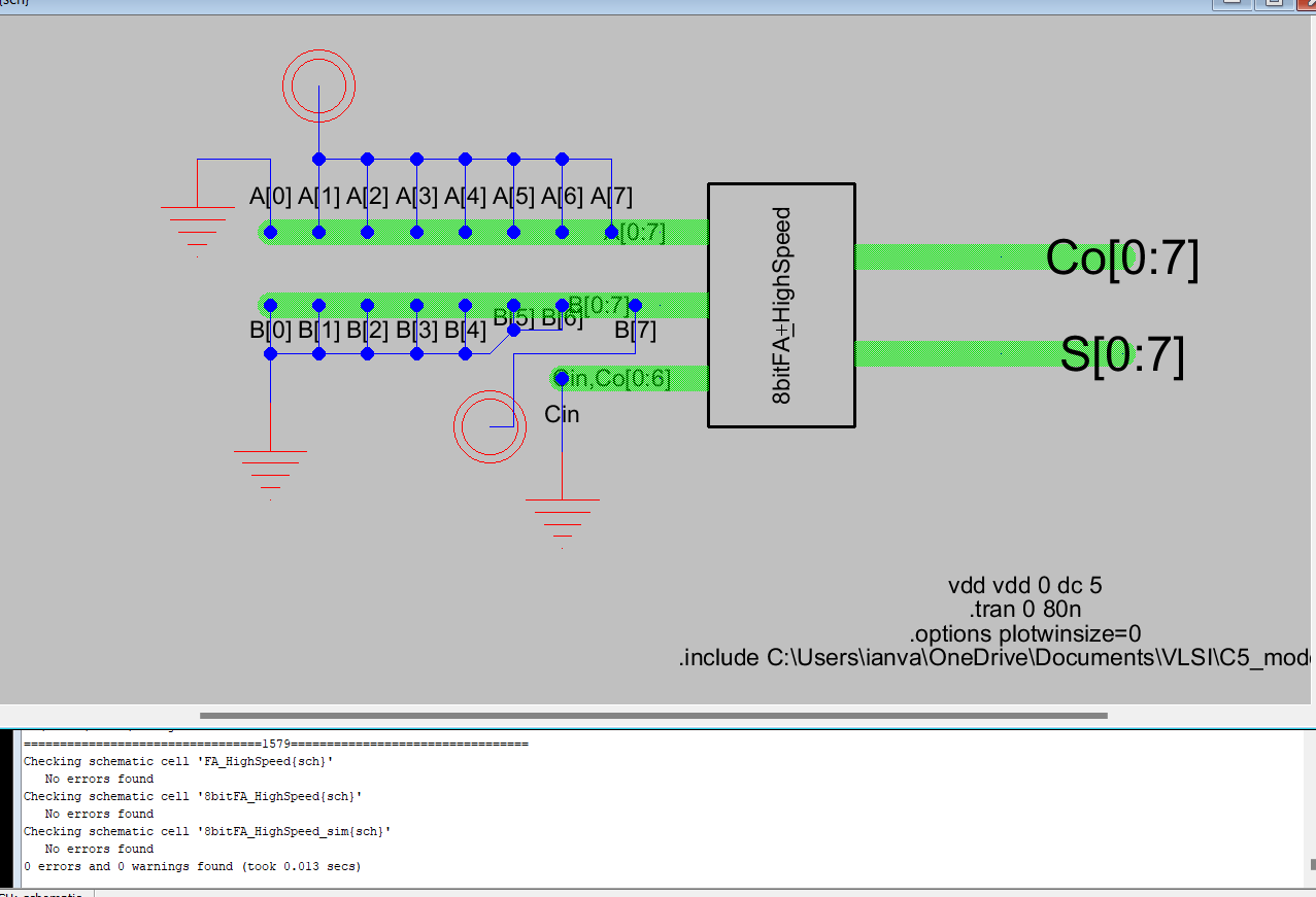
Figure 14: 8 Bit High Speed Full Adder Simulation Schematic
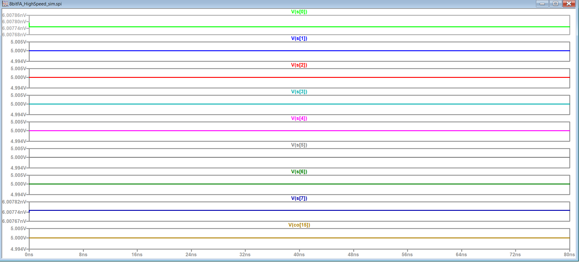
Figure 15: 8 Bit High Speed Full Adder Simulation SPICE Results
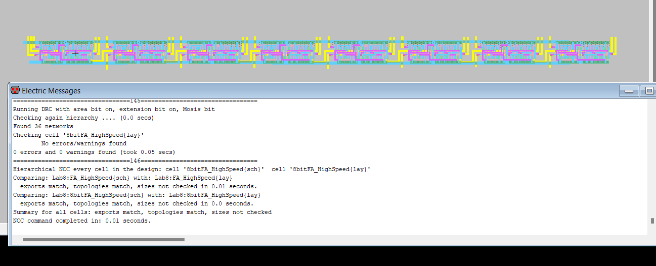
Figure 16: 8 Bit High Speed Full Adder Layout
Conclusion: This lab sucussfully taught how to design and lay out 8 Bit versions of the MUX and High Speed Full Adder