ENGR 338 - Lab 2 2023 Fall
Name: Ian Van Horn
Email: imvanhorn1@gmail.com
R-2R DAC in Eletric VLSI
This lab
introduces the Eletric VLSI software. LTSpice is linked to the software
and used to simulate schematics. First, a DAC from a library is used,
the a custome R-2R DAC is designed and analized. This analysis includes
finding the time dealy of the DAC.
This lab require the LTSpice software as well as a pencil and paper for
calculations
Task 1: Copy the existing ideal ADC-DAC files to your ENGR338 library and run the simulation. (30 points)
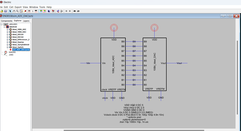
Figure 1: Layout of ADC and DAC from library

Figure 2. Simulation results of DAC in LTSpice
Task 2: Build the schematic of the R-2R DAC and run the simulation. (30 points).
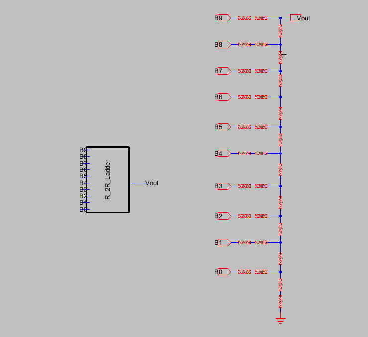
Figure 3: Layout of R-2R DAC
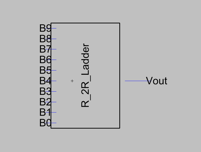
Figure 4: R_2R Icon
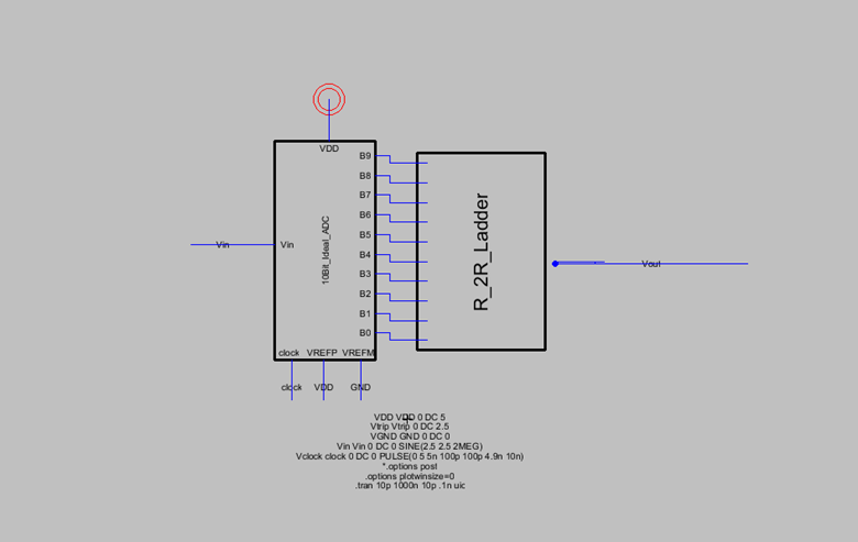
Figure 5: R_2R DAC attached to ADC from library
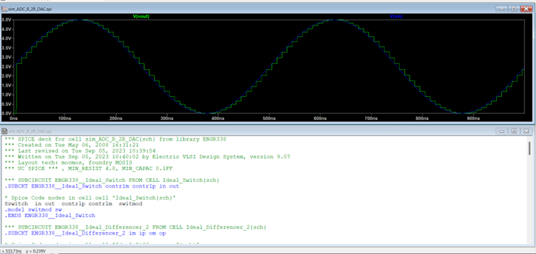
Figure 6: R-2R DAC LTSpice simulation
Task 3: Test the time delay from the B9 pin when the DAC drives a 10 pF load. (30 points).
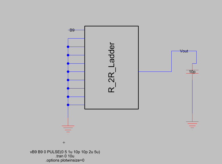
Figure 7: Layout for time delay analysis
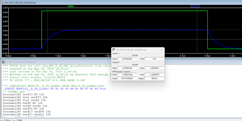
Figure 8: LTSpice analysis of time delay
Conclusion: This lab sucessfully taught how to use LTSpice inside Eletric VLSI and how to layout a basic DAC