Introduction
In this class we developed a Power Module to be utilized in future lectures. The module needed to provide 4 different outputs; 5v - 1A, 5v - 3A, 3.3v - 1A and 3.3v - 3A. The input for our module was 110 VAC, so it is basicly a AC-DC converter (transformer) on a PCB.
We used Eagle to designed the PCB, new libraries with new components were created. The guide lines and procedure were provided and can be found at yilectronics.com.
Some components were found in SparkFun library and some were generated in Texas Instrument TI.com. using a software to calculated the exact component needed for the project. Then, a the schematic was created(Fig 1) and the layout of the PCB(Fig 2).
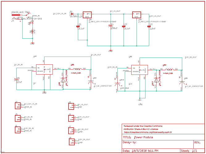
Figure 1. Schematic of the full PCB.
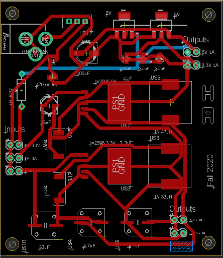
Figure 2. Layout of the PCB.
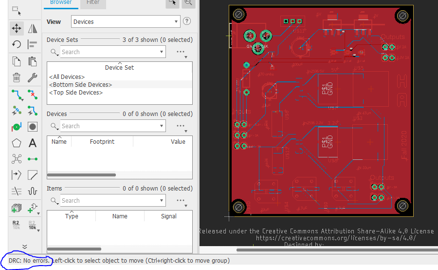
Figure 3. DRC check for errors.
After the disign was complete, PCB was ready!, pcbway.com was utilized to check our boardand for any errors before to start the process of manufacture. To get to this point, a gerber file must be obtain in Eagle in the icon CAM Procesorr, process job, save, and upload a zip file that contains the gerber files and the drill files together to their webside PCBWAY, an acount might be created to do this. PCBWAY has a software to submit the board to revision and they will give you the aproval.
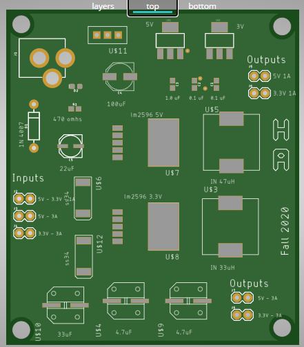
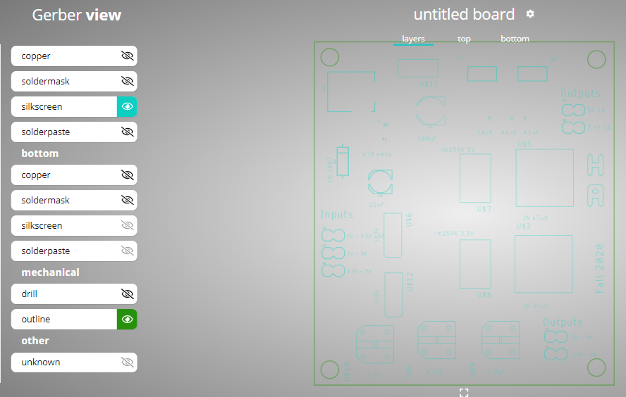

Figure 4. A layer view of the PCB final, silkscreen and solder mask respectively.
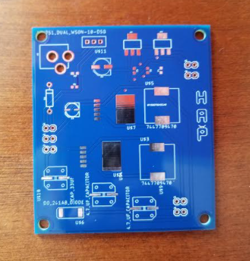
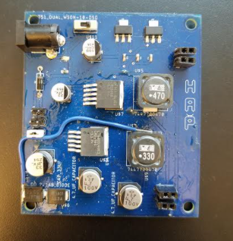
Fugure 5. PBC from manufacture with no components and with components.
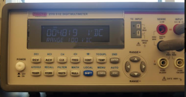
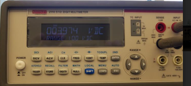
Figure 6. Testing the outputs for 5v and 3.3v with 1A.
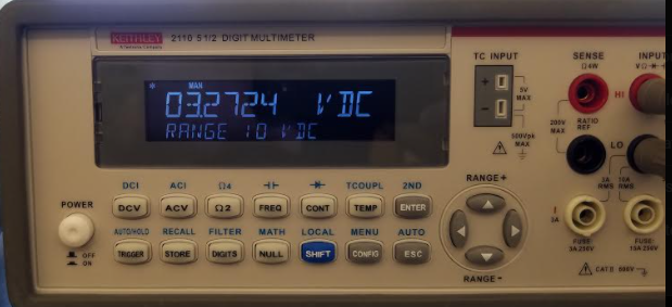
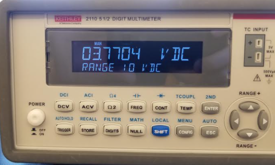
Fugure 7. Testing the output for 5v and 3.3v with 3A.
Discussion
In this project it is asummed that the student already knows how to used Eagle and pcbway.com. The challenges were in building up the new libraries and some mistakes while making the layout in Eagle. There were 2 mistakes made in this procedure. They have been corrected in the process. We will have to send the fix design to be manufacture again. So for the purpuse of this lab, we used this first PCB. There was a diode left out in the disign and the power in is been shorted with a resistor, so the output is less than what we should get for the 3A outputs. Also the LED indicator is been shorted and is not functioning. We added the diode to see if we obtained better output but since the input acts like a voltage divider, we were able to make it work. Over all a great lecture and experience on design a product and make it to come to life.