ENGR337 Lab 2020 Spring
Lab 2
Name: Humberto Arredondo Perez
Email: harredondoperez@fortlewis.edu
1. Title: More Spice and Compensated Probe
2. Introduction
In this lab we will
do simulations in LT Spice to get more familiar with the software
building a few circuits and understanding the mechanism of the
compensated scope probes.
3. Materials and Methods
LT Spice
|
Resistors
| Function Generator
|
Breadboard
|
KompoZer
| Multimeter
|
Capacitors
|
Oscilloscope
| FileZilla |
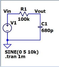
First, for task 1.1. We
built the circuit using symbols showing in Figure 1, used transient
analysis to simulate the
voltages at Vout and anylized the results. For task 1.2a on Figure 2,
we changed the voltage to 2v, for 1.2b, we change V to be 5v, Ton and
Tperiod to 1u and 2.1u separately, then on 1.2c, we reset everything to
original and replaced the 100p with a 10p capacitor, and dfinally, we
reset it and change the resistor for ohm.
In task 1.3, we built the circuit
showing on Figure 6 on the breadboard, we displayed the signal on the osilloscope and measured the time delay .
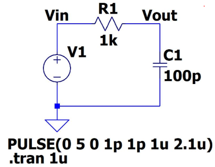
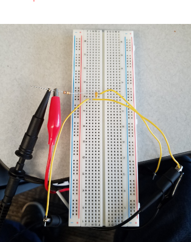
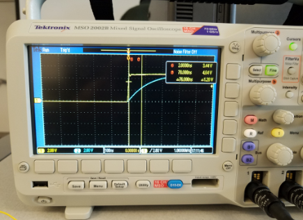
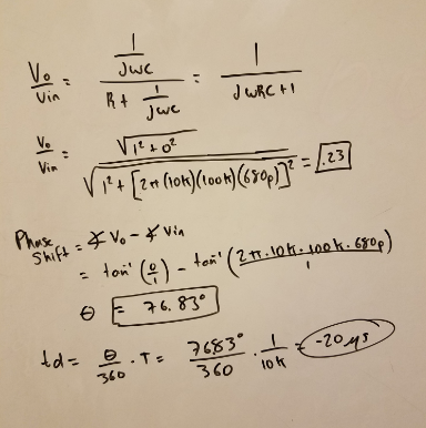
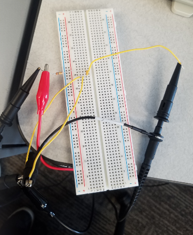
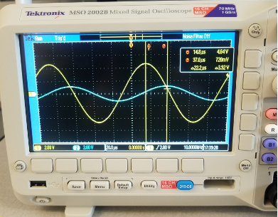
For task 2.1 we built the circuit in Figure 7 on the breadboard and
also in LT Spice, We calculated, simulated and measure the time delay
and Vo/Vin of this circuit.
In task 3, we learned about the circuit model of the oscilloscope probe we used in lab.
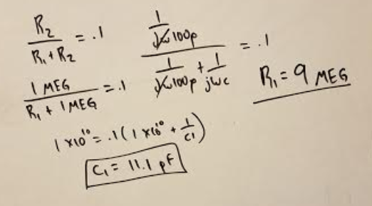
In task 3.1, We used circuit from figure 8 to attenuate the DC voltage
first, we built the circuit in LT Spice, design the unknown resistor
value to make Vo/Vin = 1/10, in DC.
And finally, in task 3.2, We took the circuit from Figure 9 and design the capacitance value.
4. Results
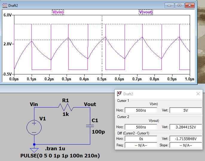
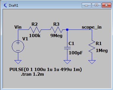
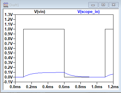
Figure 1 Original circuit and behave.
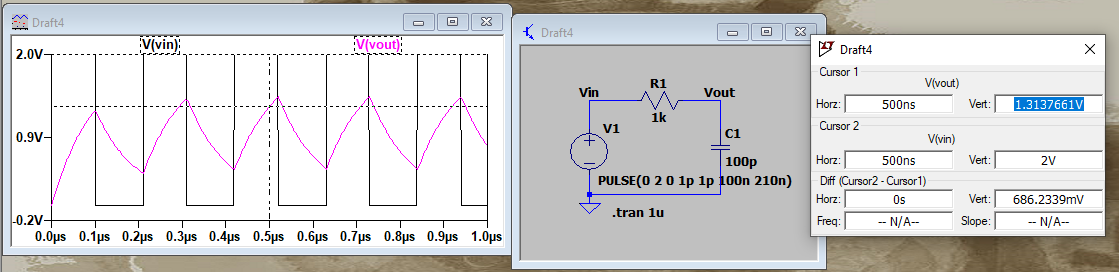
Figure 2 Circuit with a reduce voltage from original, from 5v to 2v.
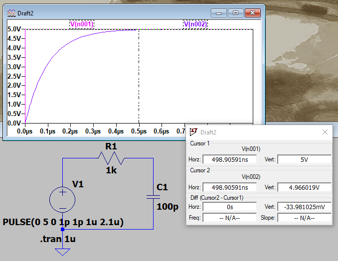
Figure 3. 5v, 1u, 2.1u and .tran 1u. changed.
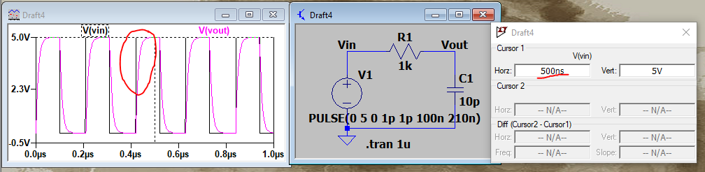
Figure 4. Original parameters, now using 10p for Capacitor.
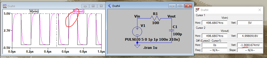
Figure 5. Original parameters, now using 100 resistor instead of 1k.
Figure 6 Schematic for task 1.3, breadboard,oscilloscope square signal shoing the cap fully charged and calculations.
Figure 7. Circuit for task 2.1, schematic, breadboard, oscilloscope, function generator and calculations for a 10x attenuation.
Figure 8 Circuit for task 3.1 Compensated probe for 10 DC Attenuation.
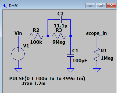
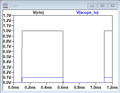
Figure 9 Circuit for task 3.2 Compensated probe for 10 DC and AC Attenuation.
5. Discussion
In this lab we used LT Spice to keep getting to know how powerfull
tool it is. We saw the different changes that affect a RC circuit and
how the signal changes while changing the components for better ability
for charging to the full capacity, and the other circuit we can see how
all the different methods match just fine. and we learned to attenuated
the DC and AC signals. Defenally a great Recap for LT Spice.