1. Title: LT Spice and edit your webside for your Lab Report
2. Introduction
In this lab we will use the method of coding (instead of schematics) to
do simulations in LT Spice, using a text file and transient analysis to
simulate the voltages using a few circuits given. Our goal is to
generate the input and output of a signal, identifying the time
delay ,to generate a DC sweep, AC sweep and DC pulse, resistor color code
and recall how to edit our website for the report.
3. Materials and Methods
LT Spice
Resistors
Breadboard
KompoZer
9V AC/DC Converter that Provides 5V
NotePad
FileZilla
Multimeter
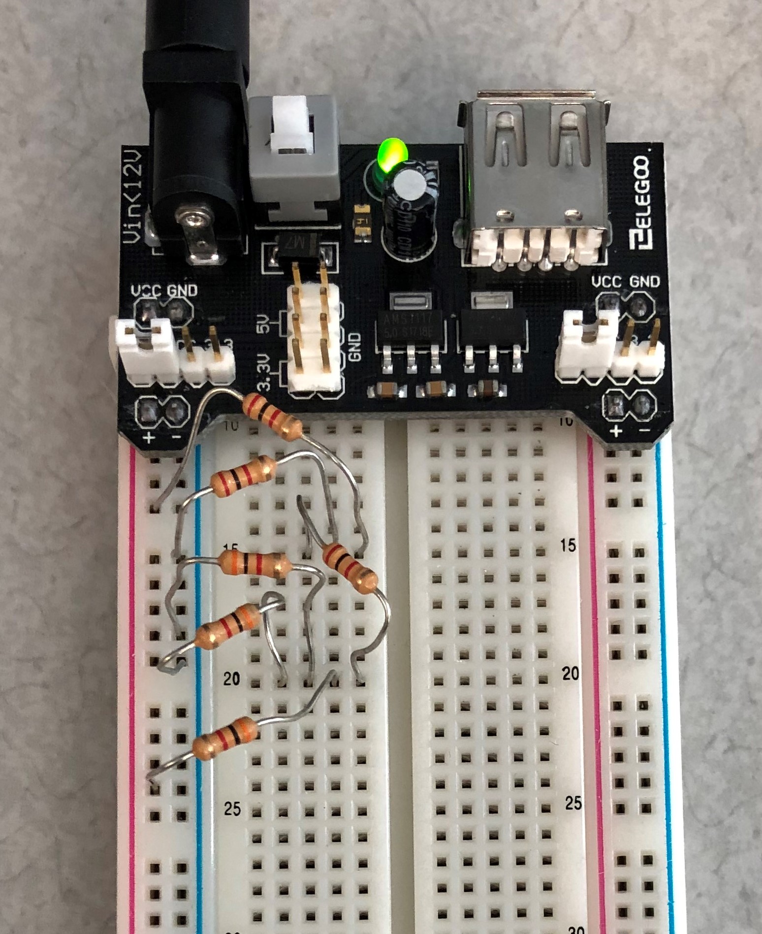
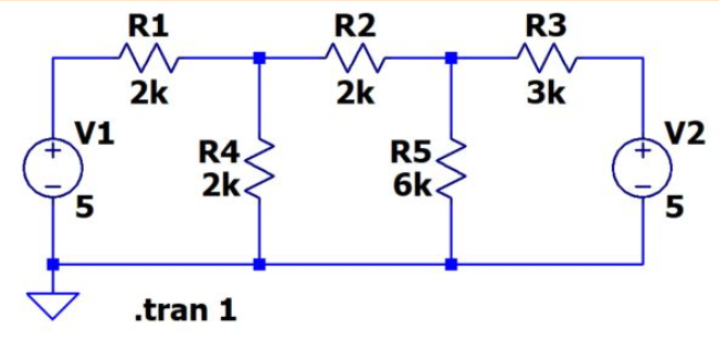
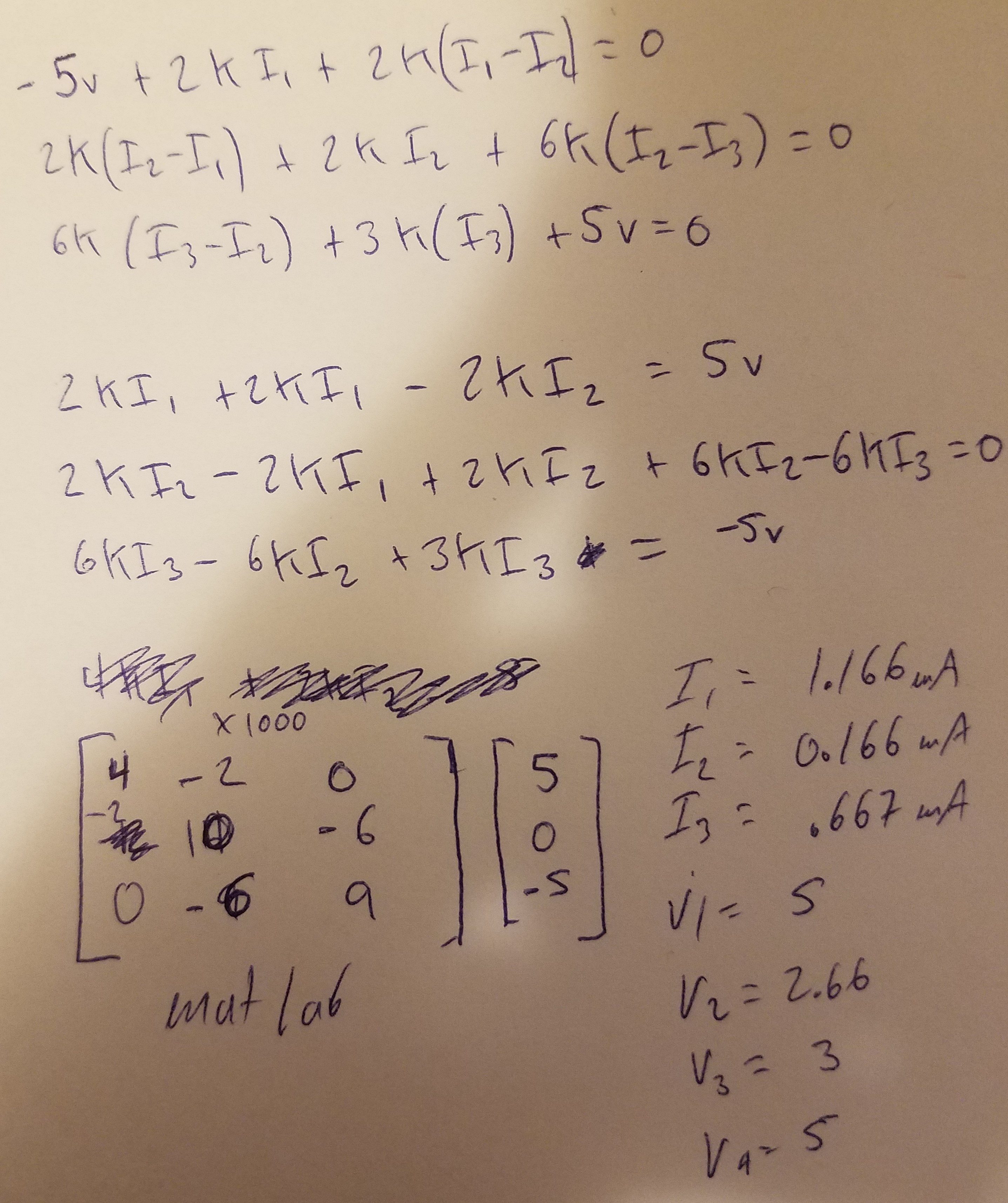
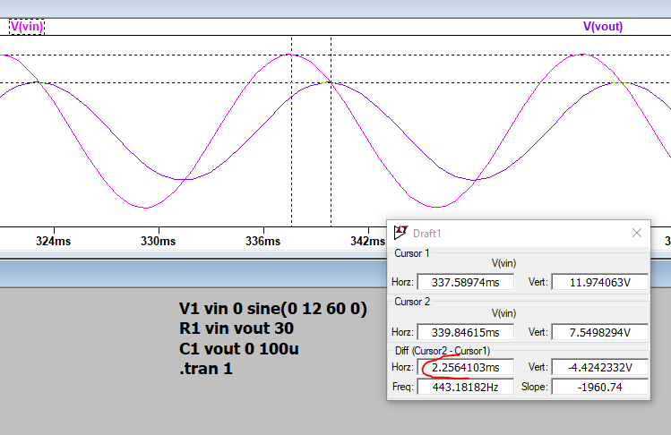
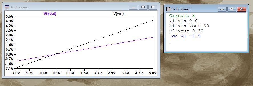
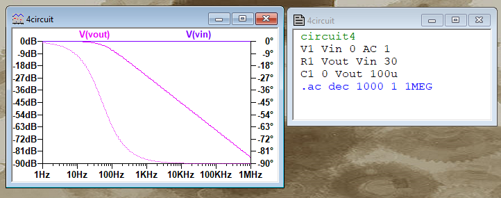
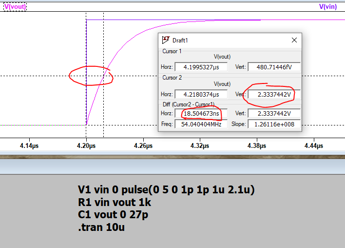
First, for task 1 we created a text file and wrote a code for the
circuit showing in Figure 1, used transient analysis to simulate the
voltages at all nodes. we built the circuit in a breadboard to check the
voltages with the multimeter and we did the calculations by hand and we
compared all the results in Table 1. In task 2, we wrote the code for the circuit
showing on Figure 2, we displayed the signal, measured the time delay
and the amplitude attenuation of the output signal compared to the
input. For task 3 we did a DC sweep from -2v to 5v, the X axxis being
the sweep of dV for the Vin and the Y axis being the voltage in terms
of the input(used Figure 3). In task 4, we did an AC sweep where the X
and Y axis represent frequency and amplitude respectively, we did units
in decades of increments, plot 100 points per decade staring from 1 Hz
to 1MEG H, we used the circuit in Figure 4. And finally, in task 5, we
used a DC pulse as the input voltage source to drive a Capacitor, wrote
the code to implement the circuit in Figure 5 and measured the time
delay.
4. Results
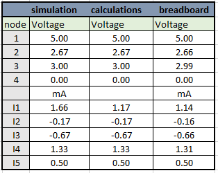
Table 1 comparison of calculations using the three methods
Figure 1 schematic, circuit 1 in a breadboard and hand calculations
Figure 2 Amplitude attenuation of 0.62, and a time delay of 2.26ms
Figure 3 Voltage sweep simulation done by coding
Figure 4 AC sweep simulation by coding
Figure 5 pulse on this circuit and time delay 18.5 ns
5. Discussion
In this lab we used 3 methods to calculate the voltage at different
nodes of circuit 1, the results shown that all the numbers matched
really well, just a minor difference on a few due to the internal
resistance of the equipment used. On the tasks from 2 to 5 we just
practice simulations by coding instead of schematics for practicing
with LT Spice and to calculate the time delay 2.25 ms on circuit 2 and
18.5 ns in circuit 5. We went over resistor color code when building
the circuit 1 in the breadboard.
This lab was a good refresher from previous classes.