CE432 Robotics II
Fall 2021
Tutorial 3: Joystick
Humberto Arredondo
harredondoperez@fortlewis.com
Joystick and stepper motor
1.- Introduction
In this tutorial the students were assigned to control a
stepper motor with a joystick. The analog signal of the joystick was processed
by an Arduino (transmitter) that then sent the information to another Arduino
(receiver) through a pair of Open-Smart 2.4 GHz transceivers modules that are
wireless. The receiver Arduino sends the commands to the step motor using a
motor driver A4988 module.
The equipment and materials used for this tutorial was:
DC to DC Power Supply (5V, 3.3V)
Breadboard
A4988 modules
Joystick
Arduinos
Open-Smart 2.4 GHz transceivers
Nema 17 stepper motor
Jumper cables
Banana cables
2.-
Methods and Results
Task 1
For this task, we needed to pair up
the joystick with the Arduino uno to understand how this worked. We
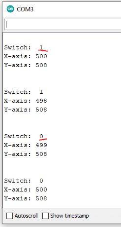
observed the serial monitor results (Figure 1).
Figure 1. Results from the connection between joystick and Arduino.
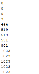
The joystick is a bi-directional potentiometer, left goes to 0, center
is about 500 and right goes to 1023 or closer. We can see the behave of
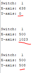
the joystick on one of the x-axis in Figure 2.
Figure 2. Values change when the joystick is moved across the x-axis.
the switch is the z-axis and is only a push buttom that has an on or
off option.
Task 2
For this task, we paired up the Open-Smart 2.4 GHz transceivers to
the Arduinos to make sure we can transmit information. The connections
are
shown in Figure 3, and the serial monitor characters transmitted are
shown in Figure 4.
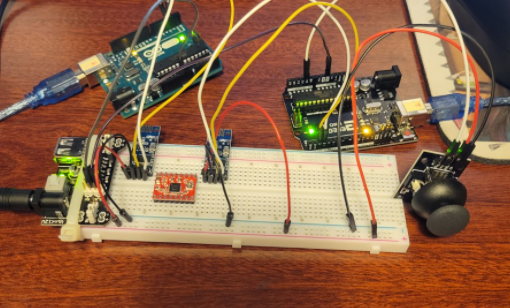
Figure 3. The Arduino in the right uses the Open-Smart module on the
right to send an information to the receiver Open-Smart module on the
left side, and this information is processed by the Arduino receiver on
the left that displays this information in the serial monitor.
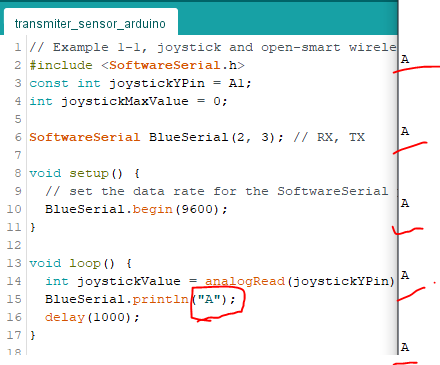
Figure 4. A Character A sent
from Arduino transmitter to receiver using the Open-Smart modules.
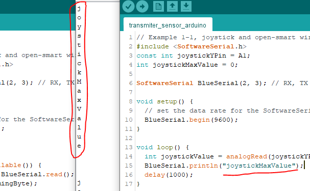
Then we connected the joystick to the Arduinos to make sure we can also
send information. The connections are shown in Figure 5 and the serial
monitor on Figure 6.
Figure 5. Same set up from Figure 3 with an
addition of Joystick.
Figure 6. Information was sent and received using the joystick.
Task 3
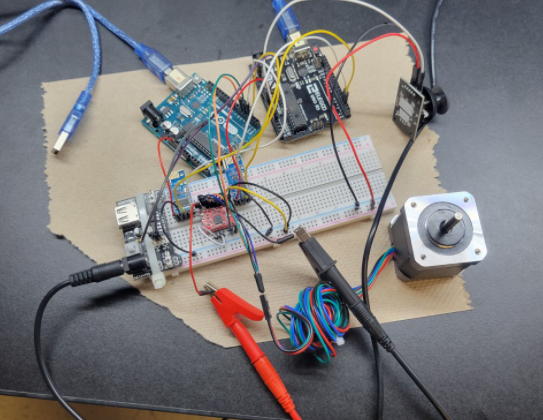
In this task, we repeated the process but now using the NEMA17 stepper
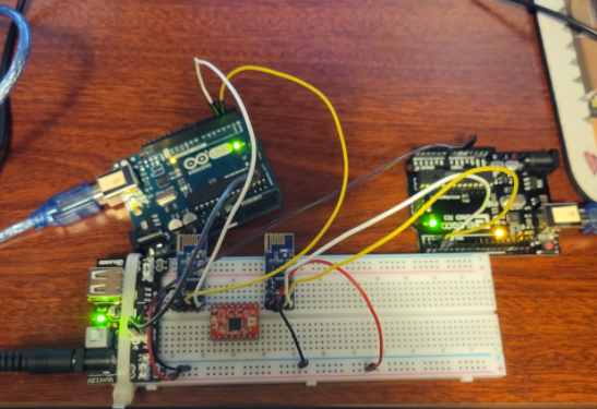
motor. We can see the connections in Figure 7.
Figure 7. The full connections from previous examples with the stepper
motor.
Figure 8. Demostration of the working project.
Discussion:
The joystick project was fun to work with, but it had some challenges. It
took me some time to figure out that the breadboard was not working
property. I attempted to use Arduinos nano in the begginning but some
some reason the code sometimes would load and sometimes woundn't. I
think the breadboard was shorted somewhere. After replacing the
breadboard, I encountered a new problem, and it took me some time to
figure out that one of my connections was not correct. Other good point
is that this Open-Smart 2.4 GHz modules don't have an address so if you
are working closed to another one, the information that is being send
it might not go to the receiver you want. Overall a great and
successful project.