CE432 Robotics II
Fall 2021
Tutorial 3: ESP32-CAM
Humberto Arredondo
harredondoperez@fortlewis.com
Using ESP32-CAM
1.- Introduction
In this tutorial the students were assigned to do more challenging
tasks using the
ESP32-CAM module and its video options using the Web Server. Also, they
were able to paired up a sensor to measure altitude, temperature and
presure.
The equipment and materials used for this tutorial was:
DC to DC Power Supply (5V, 3.3V)
Breadboard
ESP32-CAM module
FTDI Cable
Jumper Cables
External WiFi Antenna
SD card
Robot car kit
Motor driver
BMP180 sensor
LM2596 module (voltage regulator)l298m
L298n motor driver
hardware
2.-
Methods and Results
Task 1
For this task, a code for streaming
video in a Web Server was loaded to the ESP32-CAM module and It was
found in Rui's textbook. After loading the code and copying the IP
address i the browser, an image of the web Browser can be seen below in
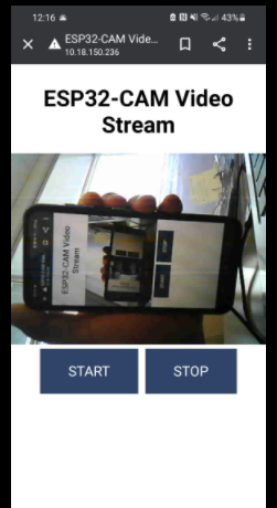
Figure 1 . This also worked in a cellphone (Figure
2).
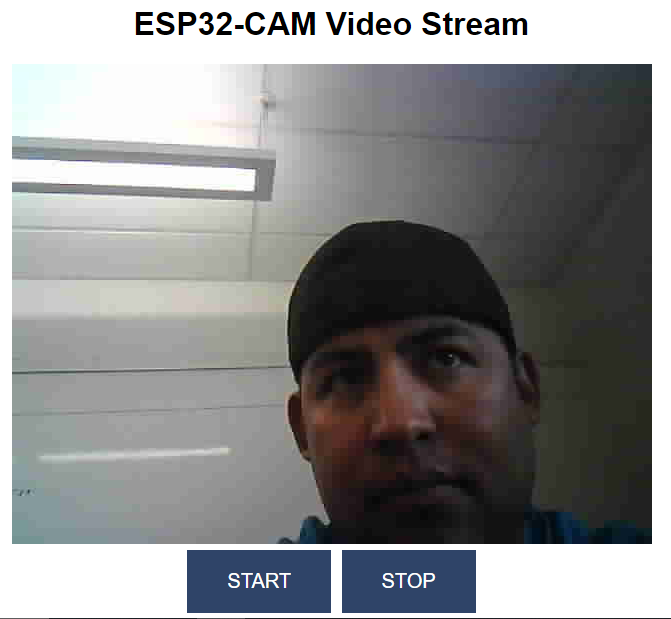
Figure 1. Image shows myself while working on this video streaming.
Figure 2. Screenshot of the streaming video working on a cellphone.
Task 2
For this task, A webserver was used to displayed Temperature,
Pressure
and Altitude. This data was obtained by a BMP180 Sensor. In order to
make this possible, the
librarys of ESPAsyncWebServer and the AsyncTCP were installed in
the Arduino IDE. Code from Rui's book was used for this
tasks, but some changes needed to be done. After adding the WiFi
credentials to the code, the IP address was obtained from the Serial
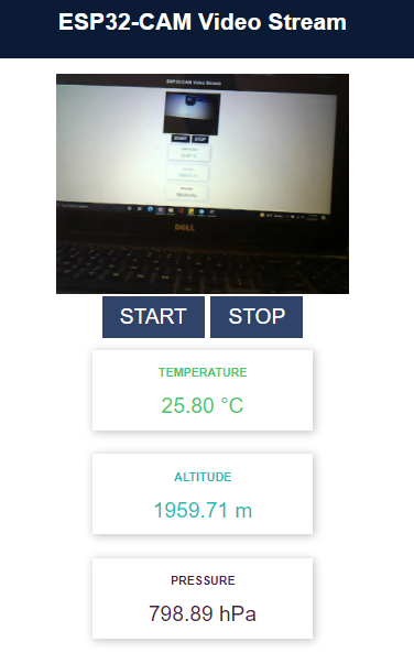
Monitor and copied to the browser. In Figure 3, these measurements can
be seen. In Figure 4, the altitude of Durango, Colorado obtained from
Google can be observe, and compare to the value was obtaing by the
sensor.
Figure 3. Web Server is displaying the video streaming, Temperature,
Altitude and Pressure.
Figure 4. Durango, Colorado's
altitude obtaing from Google.
Task 3
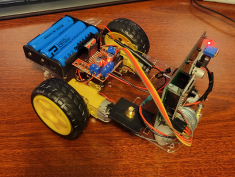
In this task, the ESP32-CAM was used to added to a remote controlled
car robot with a camera that was able to be controlled from a Web
Server. In the Web
Server 5 different functianlity buttons were made (Forward,
Backward,Left, Rigth and Stop). This robot car has 3 batteries that
provided a total of 11.1V that power up directly the L298N motor driver
and also a voltage regulator that reduces the voltage to 5V that powers
the ESP32-CAM module. After some soldering and changes to the code
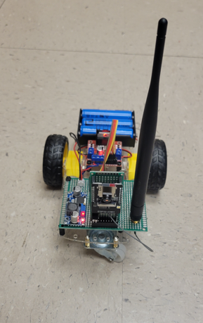
provided from Rui's textbook, the front view of the finalized product
can be seen in Figure 5, below. The side view can be seen on Figure 6.
On Figure 7, a short video of the car functioning using the commands on
the Web Server is shown.
Figure 5. Kit car front view.
Figure 6. Robot car side view.
Figure 7. Robot car demostration of the final product functioning.
After we confirmed that everything is working properly, we designed a
PCB for the robot car in EAGLE. Creating a PCB is a great way to clean
up the project and help with cable management. The schematic and layout
of the PCB is show below.
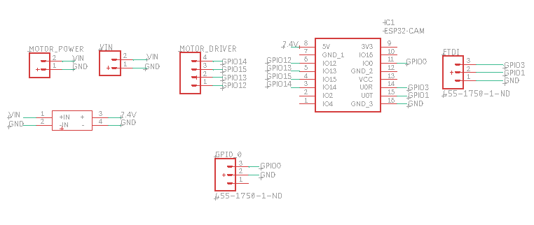
Figure 8. Schematic of the PCB.
The schematic showed in Figure 8 contains an ESP32-CAM module, pins for
the motor driver, two power connections, a three pin connector for
programming reasons and a jumper for when code replacement is needed.
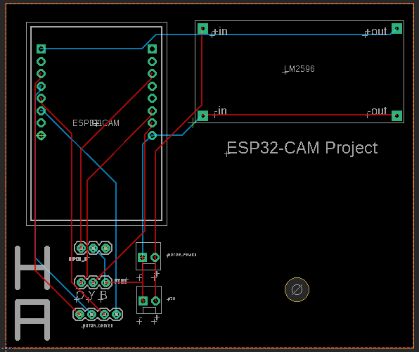
Figure 9. Layout of PCB.
The layout in this PCB showed in Figure 9 shows the final look of the
PCB it self. The hole in the bottom is there for a L-bracket that will
hold the PCB to the chasis of the Robot Car.
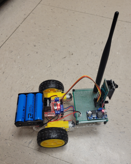
Figure 10. Robot car with PCB installed final view (missing the
antenna).
In Figure 10 the antenna was not capture at te time the picture was
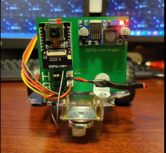
taking. we can see the functioning Robot Car with the PCB in Figure 11.
Figure 11. Final Product.
Discussion:
This robot car tutorial was the most exciting
one because the students were able to do hands on assembling this car kit and,
modified the code provided to make it work. The students discover a handful of
new applications for this module. In this process were a lot of issues such as
module's Wi-Fi misfunctioning, code for wheels troubleshooting, faulty camera
and rotating the image 90 degrees. The PCB was designed and replaced successfully,
and all the components needed were soldered. Making the holes in the car's chassis
was challenging because the material is brittle. We can see in Figure 10 how
the car is missing some pieces.