Verilog gVim basics
Tasks:
1) Use
gvim and Vivado to simulate the examples in sections 2.1, 2.2, and 2.3.
Post snapshots of gvim windows and vivado simulation results in your
report. You must create testbenches for your simulations. (20 points)
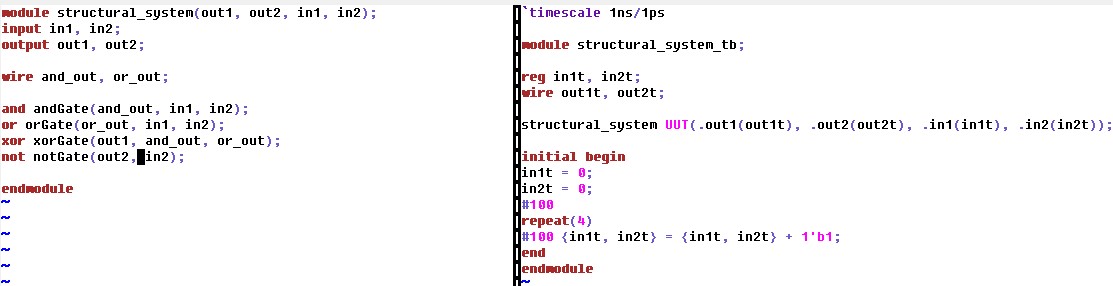
2.1 - Structural Modeling
Fig 1. gVim code for structural system module (left) and system test bench (right).
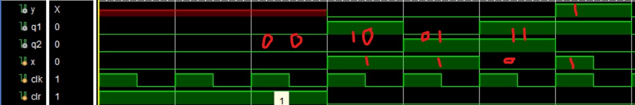 Fig 2.
 Vivado simulation for structural modeling.
2.2 - Dataflow Modeling
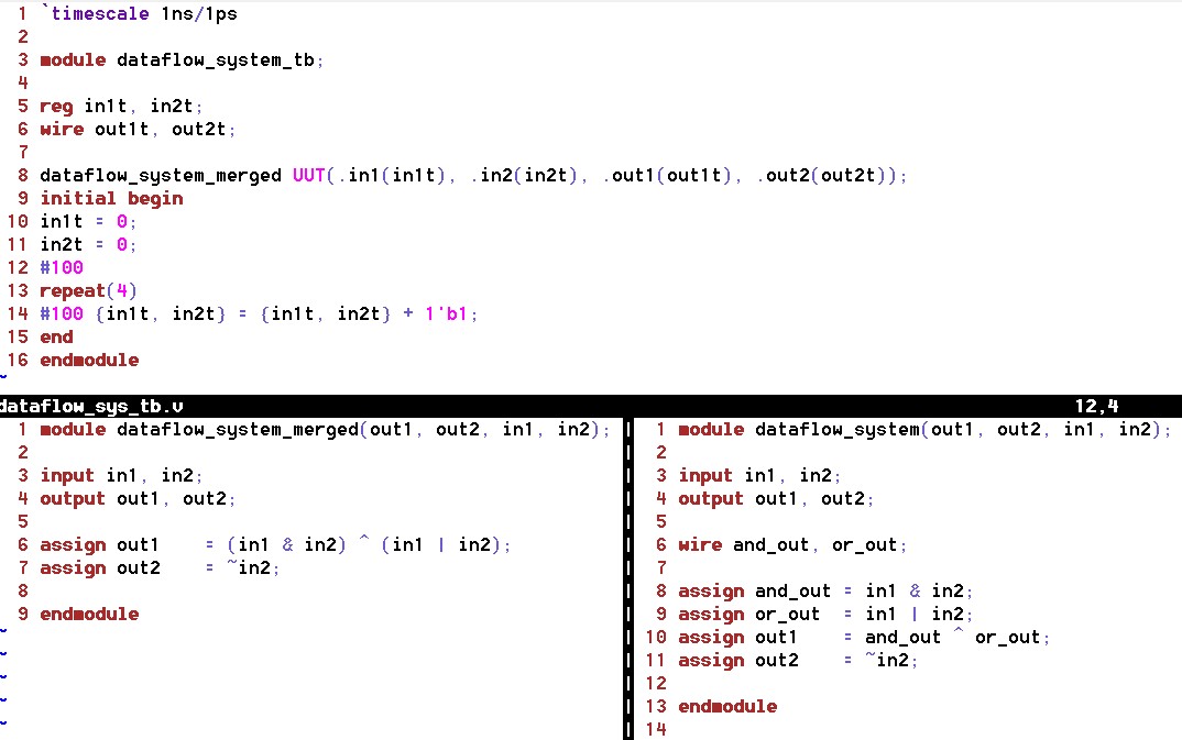 Fig 3.
 gVim code for dataflow system testbench (top), merged (bottom left), and module (right).
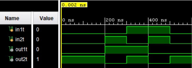 Fig 4.
 Vivado simulation for dataflow modeling.
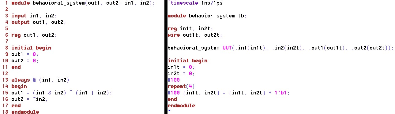 Fig 5.
 gVim code for behavioral system module (left) and system test bench (right).
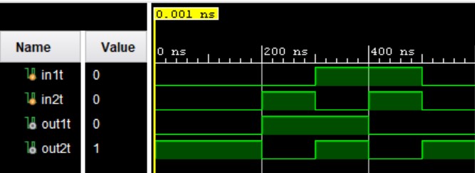 Fig 6.
 Vivado simulation for behavioral modeling.
2) Run a simulation to show the difference between blocking and non-blocking assignment in the example in section 2.4. (20 points)
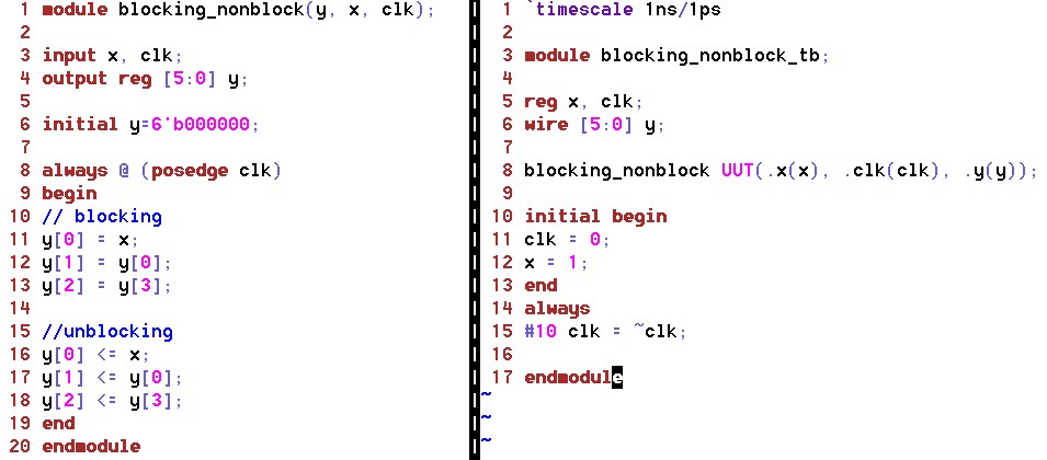 Fig 7.
 gVim code for blocking and non-blocking in a behavioral system module (left) and system test bench (right).
The blocking and un-blocking simulation should show that the first four bits are changed while the last two are unchanged do to the un-blcoking syntax (<=).
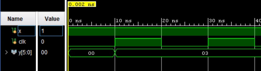 Fig 8.
 Vivado simulation for blocking and non-blocking. The output shows the value of the 6-bit output.
Running the simulation we see that the
value after the 10 ns delay the clock changes and the input, x, becomes
zero. Thus, we have the 6-bit binary number, 000011, or 3 in decimal form as seen in Fig 8.
3) Repeat the simulation example in section 2.5. (20 points)
Section 2.5 goes over axamples of timing and delay.
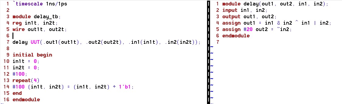 Fig 9.
 gVim code for time and delay testbench module (left) and module (right).
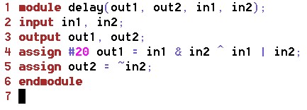 Fig 10.
 A 20 ns delay on the first ouput.
The second output is delayed by 20 ns seen on the right in Fig 9 and the first ouput is delayed by 20 ns as seen in Fig 10.
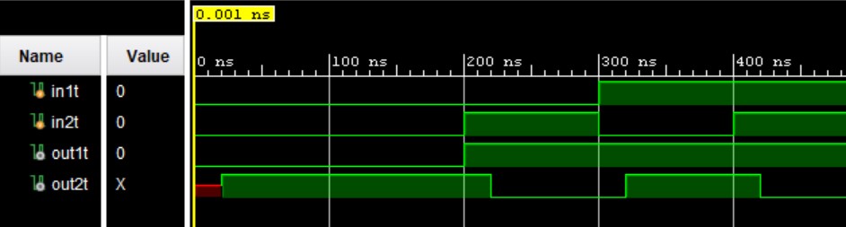 Fig 11.
 Output one with a 20 ns delay in simulation.
4) For the example in section 2.5, move the 20 ns delay from Line 25 to Line 24 and run the simulation. (20 points)
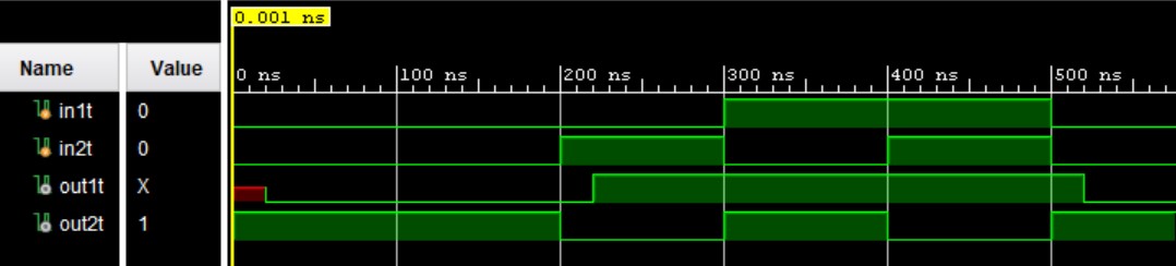 Fig 12.
 Output two with a 20 ns delay in simulation.
A diagram was hand drawn to understand the delay show in Fig 13.
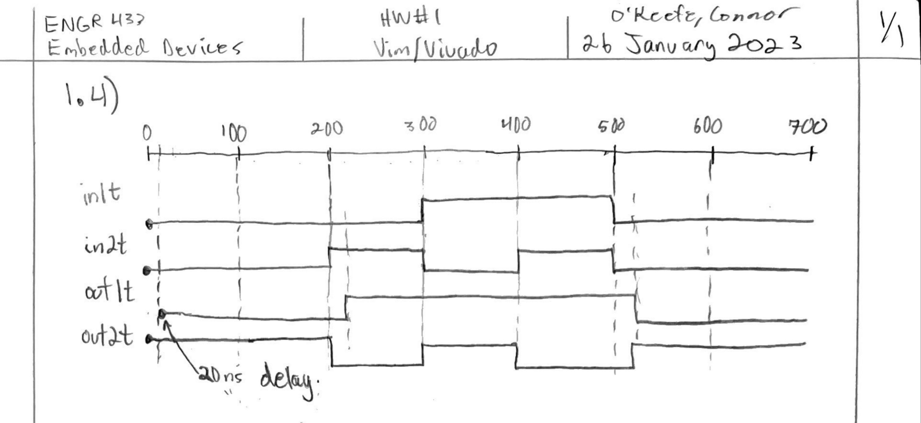 Fig 13.
 A hand drawn diagram of the simulation from section 2.5.
5) Use gvim and vivado, repeat the example in section 2.6. Post the
gvim windows and the vivado simulation windows for credit. (20 points)
Section 2.6 walked through hierarchy modules and how to code and
simulate them in Vivado. A system module was created that instantiates
an "and module" and an "or module" to show this.
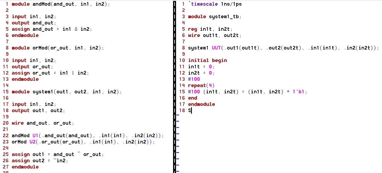 Fig 14.
 System module (left) instantiating and/or modules and the testbench (right).
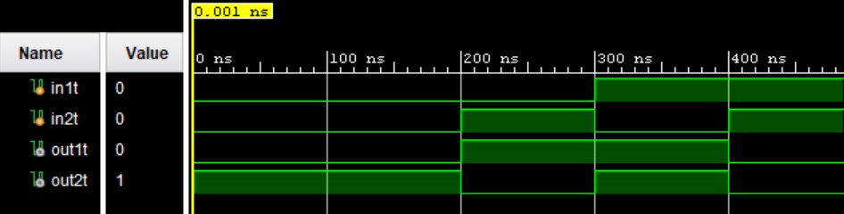 Fig 15.
 System simulation for hierarchy modeling.