CE433 Embedded Devices
Lab 4
- Combinational Blocks

Connor O'Keefe
Email: cwokeefe@fortlewis.edu

Introduction
The two goals in this lab are to first simulate traffic lights using combinational blocks and second simulate an even parity generator and even parity error checker together.

Materials and Methods
  1. Basys 3 FPGA
  2. Vivado
  3. gVim
Procedure
A truth table for the light cycle is generated and equations for each light were found using K maps. Using these equations, a module and testbench for the simulation can then be written in verilog.

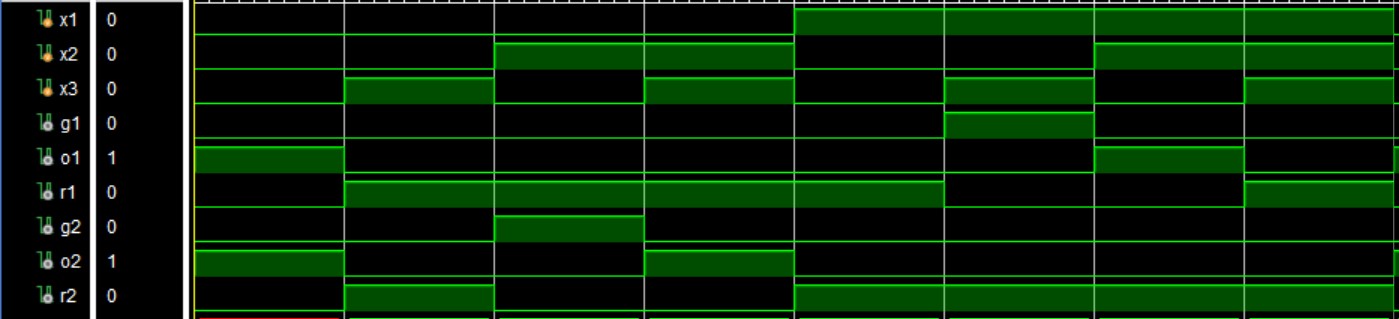
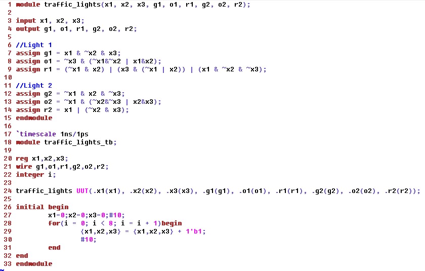
Figure 1. Verilog code for the light cycle simulation.

The light cycle may also be written for FPGA implimentation, seen in Figure 2.


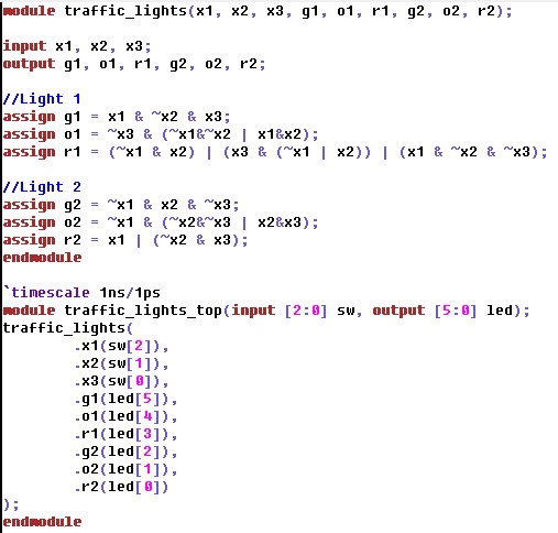
Figure 2. Verilog code for the light cycle using the FPGA.

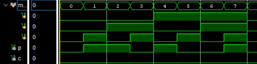
The verilog code for the even parity simulation is then written, see in Figure 3.


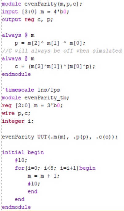
Figure 3. Verilog code for the even parity simulation.
Results
The truth table for the light cycle is show in Figure 4.

Figure 4. Traffic light cycle truth table.


The K maps show the equtions, Figure 5 and 6, for each traffic light.
Fig 1.           
(a)                                (b)                                (c)                                 (d)

Figure 5. The K maps and equations for (a) G1, (b) O1, and (c and d) R1.

       
(a)                                  (b)                                  (c)
                                                                                                                                                          
Figure 6. The K maps and equations for (a) G2, (b) O2, and (c) R1.

The simulation of the traffic light is shown in Figure 7 and the FPGA demo is shown below


Figure 7. Traffic light simulation.


The simulation for the even parity is shown below, Figure 8. The FPGA demo is shown below.


Figure 8. Even parity simulation.


Discussion
Combinational blocks are used in many real world applications. The two simulated in this lab are simple, yet we see or use these scenarios everyday.