1. Introduction
The Internet of Things (IoT) is a useful way to
wirelessly communicate data. Sometimes it is more efficient to send
data wirelessly between master and slave MCUs. Another important
concept to learn is how to save data to a SD card so that the data may
be processed later.
To demonstrate one way of accomplishing these tasks, a prototype
circuit of a portable MPU6050 accelerometer is designed using two ESP32
modules and a SD holster. The prototype will then be turned into a
wearable PCB, and any necessary device libraries will be created for
EaglePCB.
2. Materials
Breadboard
Wires for connecting
ESP32-WROOM-32D (2 of them)
MicroSD Card Adapter
ITG/MPU6050 Gyroscope/Accelerometer Sensor Duo
Resistors of the following values: 10k (2 of them)
Arduino IDE and necessary ESP32 hardware files
Computer capable of running AutoDesk software
Eagle PCB software from AutoDest
Mouse
3. Procedure
For this lab, we started by learning how to use the
ESP32 module's "boot button" to upload code. We did this by uploading a
simple sketch to blink the blue LED on one of the ESP32 modules.
A demonstration video can be seen below.
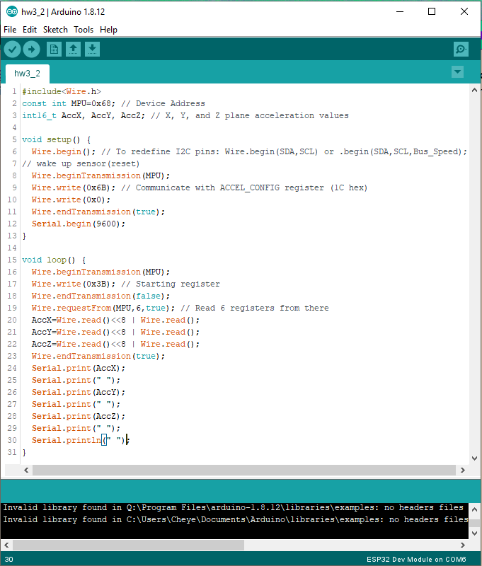
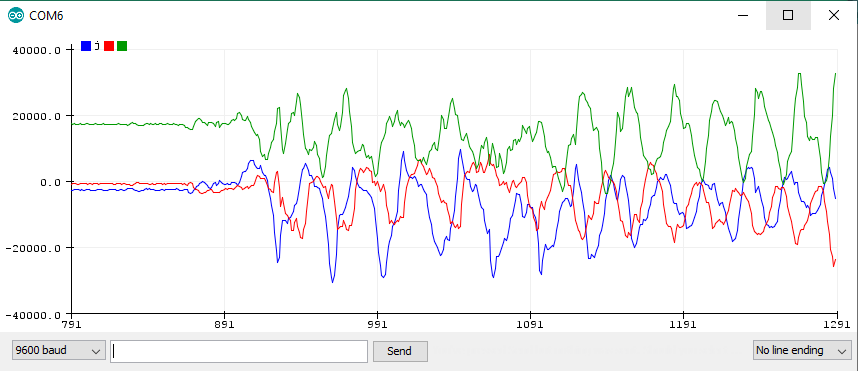
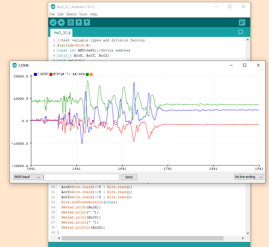
Next, the MPU6050 was connected to the ESP32 and the data was displayed
in the serial plotter. No conversions were made before plotting the
data.
Once the data was successfully aquired and sent to the ESP32, the data
type was changed from a fixed-length integer to a float, and the data
itself needed to be converted to g's in the +/- 4g range.
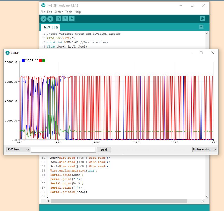
This took a few steps to figure out. First the data was just redeclared
as float type and converted to the +/- 4g range. As shown in the figure
below, this did not work
correctly.
The minimum value is 0; For acceleration, the sign indicates the
direction of movement. Another method was needed to correctly display
the data.
The next thing attempted was to remove
the conversion factor but to leave the data type as float. The figure
below shows that the changes made very little progress if any at all.
The minimum value remains 0.
Still another method was needed to correctly display the acceleration
data.
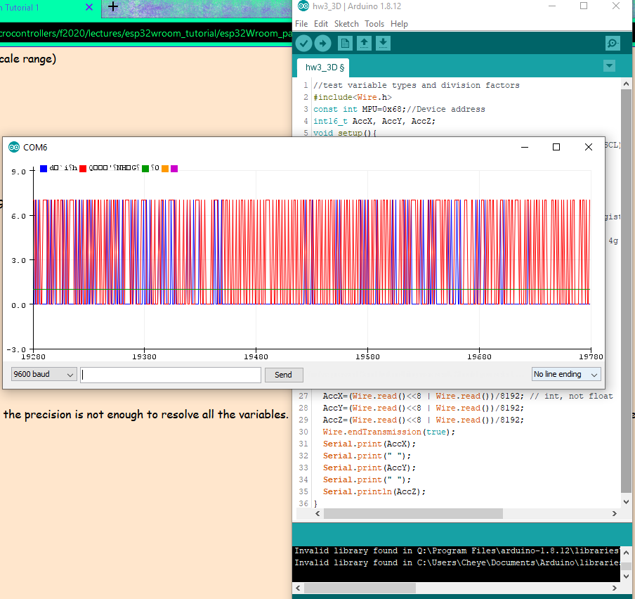
After that was done, to revert back to the fixed-length
integer type int16_t while still leaving the conversion factor out of
the sketch. The graph below shows that this removed the lower bound;
however, the data is all integer
types, and the best way to accurately represent data, especially after
being converted to differnt units, is to show a decimal value. The data
still needed to be converted to g's also.
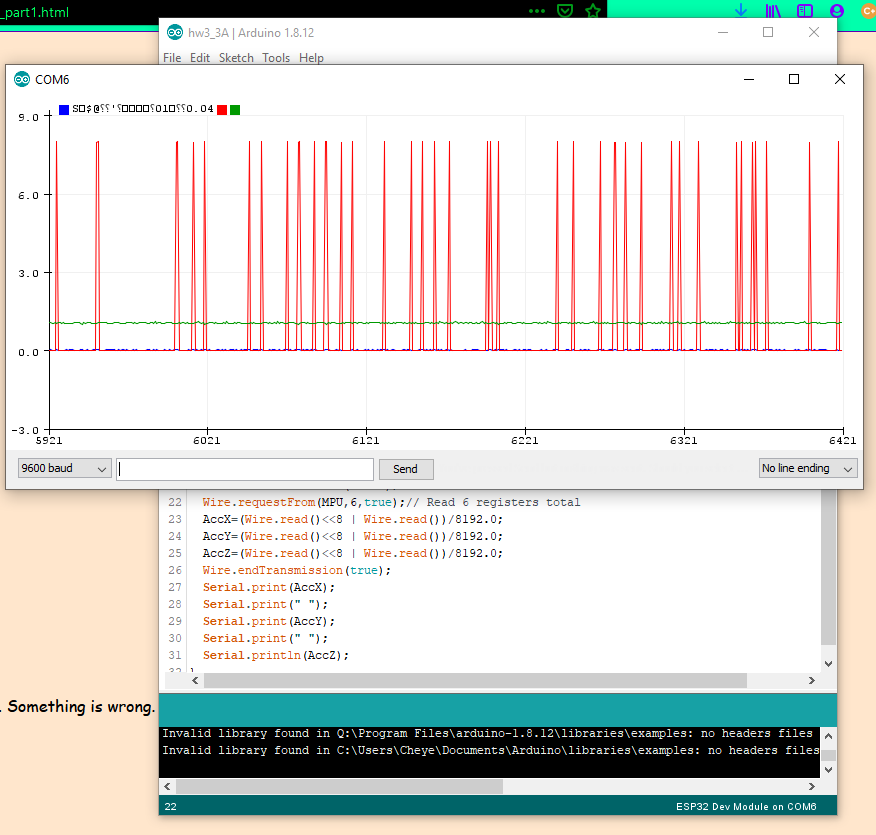
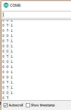
The conversion factor was represented as a float to attempt to prevent
integer division, but that did not work. The figure below is a screen
snip of the serial plotter when the conversion factor was added back in
while leaving int16_t as the data type.
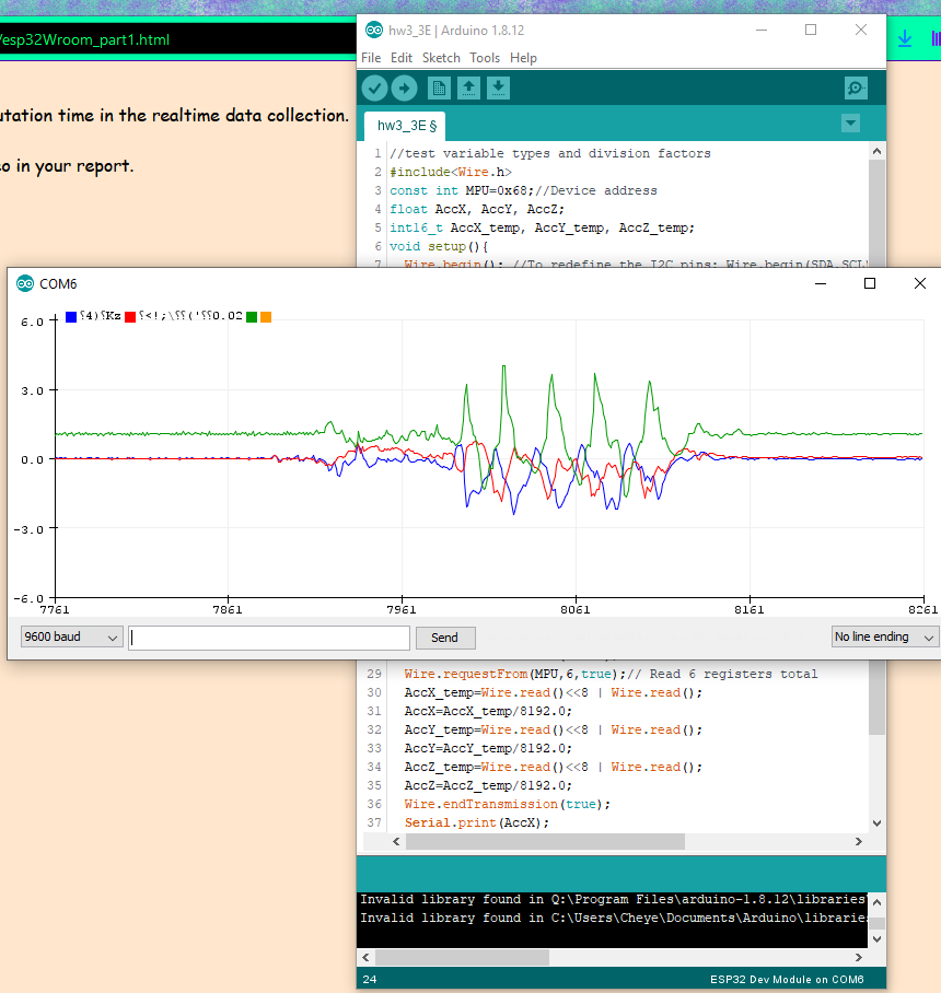
The next attempt was to declare a float type variable. These new
variables were assigned the value of the int16_t data after being
converted by the float conversion factor. As shown in the figure below,
this worked! A joyous moment!
Thank you Dr. Li for suffering through that for us!
A demonstration video of the converted data being plotted in real time.
Once the data was situated to be recorded properly, the next step was
to record the data to a SD card through Serial Peripheral Interface
(SPI) communication. SPI was used because it is a synchronous data bus
and is great for master-slave chains.
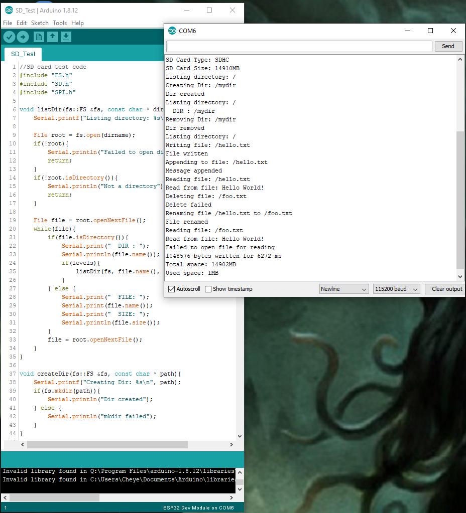
A microSD card adapter was connected to the ESP module, and a sketch
was uploaded to test the communication between the ESP32 and the
microSD adapter.
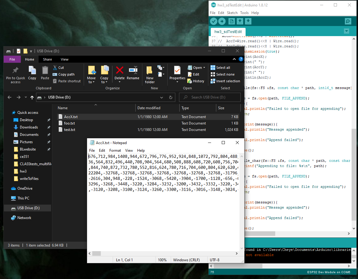
The data was stored on the microSD card in real time. It was stored in
a text file titled "AccX.txt"
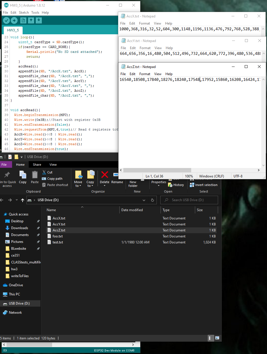
The code was modified to store the data from the X, Y, and Z axes
respectively in separate files. File names kept the same format.
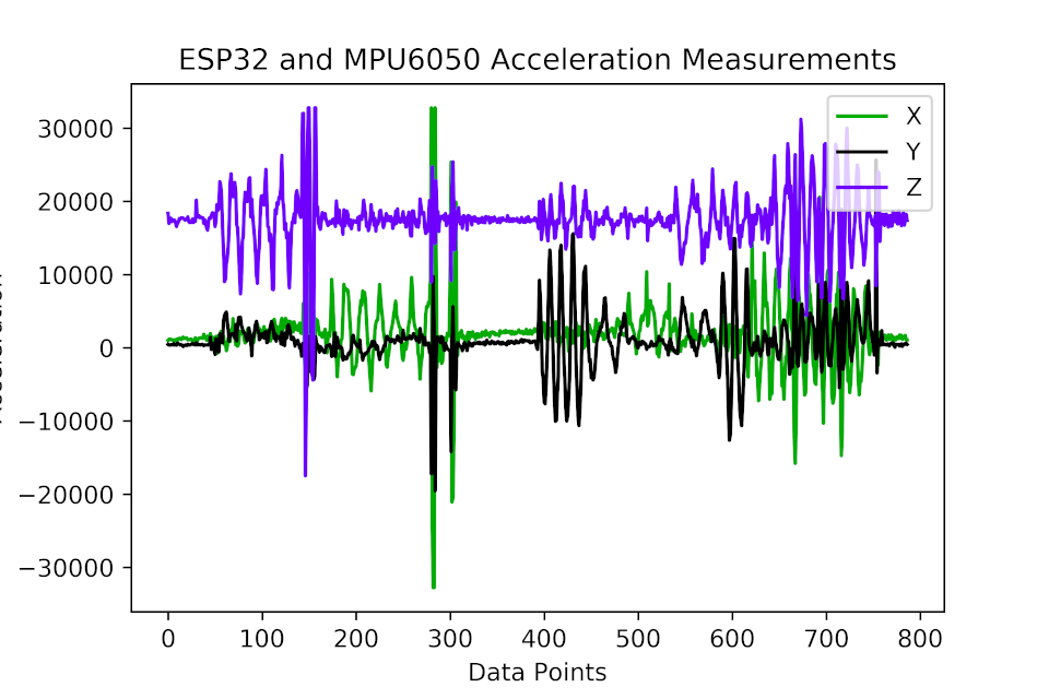
The data was then taken from the files and a Python script was written
to
plot the data using the matplotlib.pyplot library.
The data plot can be shown in the figure below.
The code was modified again to ensure that the data type being plotted
was infact of type float and in the +/- 4g range. The new data was put
into a similar Python
script to be represented in a graph. The graph is shown in the figure
below.
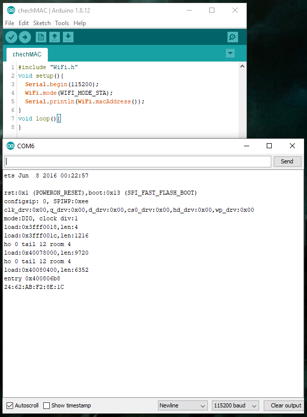
The next step was to create the master-slave circuit. First, the MAC
address was checked for each ESP32 module.
The MAC address of the "master" ESP32 module is on the right. The MAC
address of the "slave" ESP32 module is on the left.
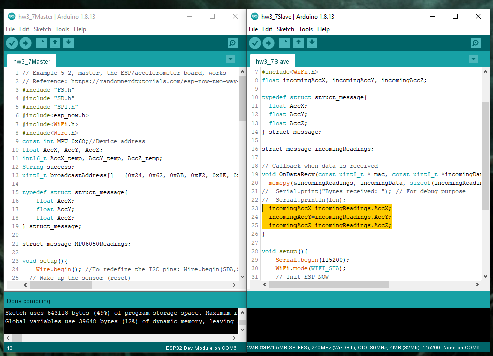
Snippets of the scripts used for the master and slave ESP modules are
shown in the figure below. The master script is shown on the right, and
the slave script is shown on the left.
The completed OnDataRecv function is highlighted in yellow.
A video demonstration of the master-slave prototype circuit.
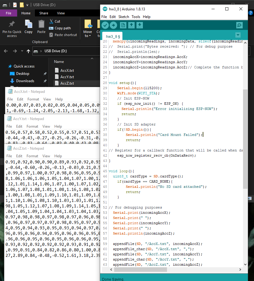
Finally, the microSD card adapter was connected to the receiving
module, and the code for the microSD adapter was added into the
sketches to allow the data to be saved onto the SD card.
This figure shows the separate files and the script.
As a finishing touch, the code was cleaned up; Any lines only for
debugging purposes
were removed, extra conversions were removed, and the sketches were
left with the bare minimum code required to function properly.
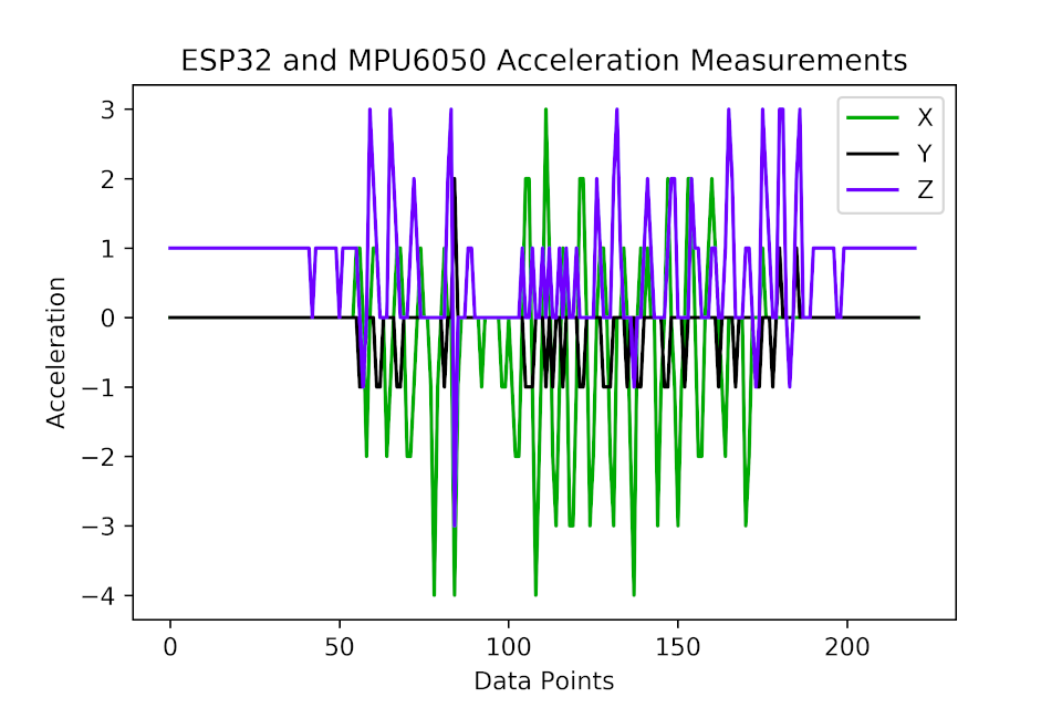
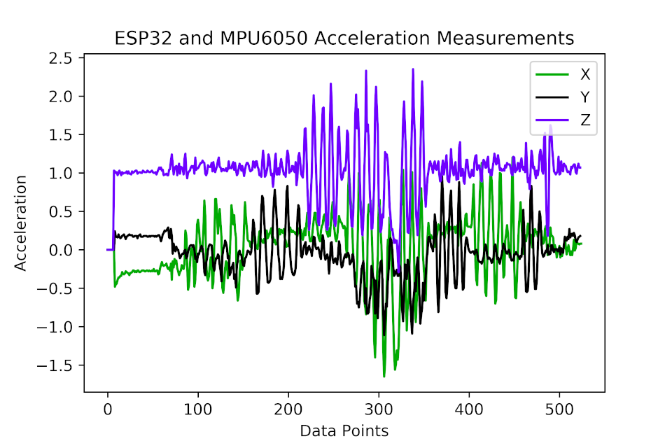
The final data set saved to the microSD card was plotted using a Python
script and the matplotlib.pyplot library. The graph can be seen in the
following figure.
------------------------------------------------------------------------------------- The code
sketches before refactoring:.
void setup(){
Wire.begin(); //To redefine the I2C pins:
Wire.begin(SDA,SCL) or Wire.begin(SDA, SCL, Bus_Speed).
// Wake up the sensor (reset)
Wire.beginTransmission(MPU);
Wire.write(0x6B);//Wake up the MPU chip
Wire.write(0x00);
Wire.endTransmission(true);
Wire.beginTransmission(MPU);
Wire.write(0x1C);//Talk to the ACCEL_CONFIG register
(1C hex)
Wire.write(0x08);//Set the register bits as 00001000
(+/- 4g full scale range)
Wire.endTransmission(true);
Serial.begin(115200); // It's fine to use a higher
speed other than 9600 but remember to change the rate in your serial
monitor
WiFi.mode(WIFI_STA);
// Init ESP-NOW
if (esp_now_init() != ESP_OK) {
Serial.println("Error initializing
ESP-NOW");
return;
}
// Once ESPNow is successfully Init, we will
register for Send CB to get the status of Trasnmitted packet
// esp_now_register_send_cb(OnDataSent);
// Register peer
esp_now_peer_info_t peerInfo;
memcpy(peerInfo.peer_addr, broadcastAddress, 6);
peerInfo.channel = 0;
peerInfo.encrypt = false;
// Add peer
if (esp_now_add_peer(&peerInfo) != ESP_OK){
Serial.println("Failed to add peer");
return;
}
}
void loop(){
accRead();
MPU6050Readings.AccX=AccX;
MPU6050Readings.AccY=AccY;
MPU6050Readings.AccZ=AccZ;
esp_err_t result = esp_now_send(broadcastAddress,
(uint8_t *) &MPU6050Readings, sizeof(MPU6050Readings)); //Send the
data. &MPU6050Readings is just a 8-bit character pointer to store
the data
// if (result == ESP_OK) { // For debug purpose
// Serial.println("Sent with success");
// }
// else {
// Serial.println("Error sending the
data");
// }
}
void accRead(){ // read the MPU data to ESP32
Wire.beginTransmission(MPU);
Wire.write(0x3B);//Start with register 0x3B
Wire.endTransmission(false);
Wire.requestFrom(MPU,6,true);// Read 6 registers
total
AccX_temp=Wire.read()<<8 | Wire.read();
AccX=AccX_temp/8192.0;
AccY_temp=Wire.read()<<8 | Wire.read();
AccY=AccY_temp/8192.0;
AccZ_temp=Wire.read()<<8 | Wire.read();
AccZ=AccZ_temp/8192.0;
Wire.endTransmission(true);
}
// Callback when data is sent, for debug purpose
void OnDataSent(const uint8_t *mac_addr, esp_now_send_status_t status) {
Serial.print("\r\nLast Packet Send Status:\t");
Serial.println(status == ESP_NOW_SEND_SUCCESS ? "Delivery
Success" : "Delivery Fail");
if (status ==0){
success = "Delivery Success :)";
}
else{
success = "Delivery Fail :(";
}
}
-------------------------------------------------------------------------------------
// Task 8 Slave - Save data to SD, works! :)
//https://randomnerdtutorials.com/esp-now-two-way-communication-esp32/
#include "FS.h"
#include "SD.h"
#include "SPI.h"
#include<esp_now.h>
#include<WiFi.h>
float incomingAccX, incomingAccY, incomingAccZ;
// Callback when data is received
void OnDataRecv(const uint8_t * mac, const uint8_t *incomingData, int
len) {
memcpy(&incomingReadings, incomingData,
sizeof(incomingReadings));
// Serial.print("Bytes received: "); // For debug purpose
// Serial.println(len);
incomingAccX=incomingReadings.AccX;
incomingAccY=incomingReadings.AccY;
incomingAccZ=incomingReadings.AccZ;// Complete the function by
filling out the blocked area
}
// Init SD adapter
if(!SD.begin()){
Serial.println("Card Mount
Failed");
return;
}
// Init ESP-NOW
if (esp_now_init() != ESP_OK) {
Serial.println("Error initializing
ESP-NOW");
return;
}
// Register for a callback function that will be called when data is
received
esp_now_register_recv_cb(OnDataRecv);
}
void loop(){
accRead();
MPU6050Readings.AccX=AccX_temp;
MPU6050Readings.AccY=AccY_temp;
MPU6050Readings.AccZ=AccZ_temp;
esp_err_t result = esp_now_send(broadcastAddress,
(uint8_t *) &MPU6050Readings, sizeof(MPU6050Readings)); //Send the
data. &MPU6050Readings is just a 8-bit character pointer to store
the data
}
void accRead(){ // read the MPU data to ESP32
Wire.beginTransmission(MPU);
Wire.write(0x3B);//Start with register 0x3B
Wire.endTransmission(false);
Wire.requestFrom(MPU,6,true);// Read 6 registers
total
AccX_temp=Wire.read()<<8 | Wire.read();
AccY_temp=Wire.read()<<8 | Wire.read();
AccZ_temp=Wire.read()<<8 | Wire.read();
Wire.endTransmission(true);
}
-------------------------------------------------------------------------------------
// Task 9 Slave - Remove conversions and debugging code, then save data
to SD, works! :)
//https://randomnerdtutorials.com/esp-now-two-way-communication-esp32/
#include "FS.h"
#include "SD.h"
#include "SPI.h"
#include<esp_now.h>
#include<WiFi.h>
int16_t incomingAccX, incomingAccY, incomingAccZ;
// Callback when data is received
void OnDataRecv(const uint8_t * mac, const uint8_t *incomingData, int
len) {
memcpy(&incomingReadings, incomingData,
sizeof(incomingReadings));
// Init ESP-NOW
if (esp_now_init() != ESP_OK) {
return;
}
// Register for a callback function that will be called when data is
received
esp_now_register_recv_cb(OnDataRecv);
}