3. Procedure
For this lab, we started by exploring how the Adafruit 128x64 OLED worked. We did this by using the example sketch that demonstrates the display's abilities.
A demonstration video:
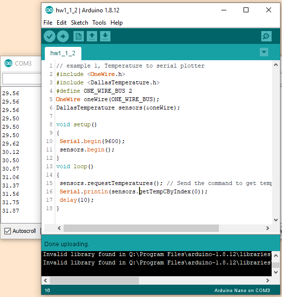
Next, the Dallas DS1820 temperature sensor was connected, and temperatures were displayed in the serial monitor.
A screen capture of the data displayed in the serial monitor:
The OLED was then connected and the temperature data was displayed on the OLED in real time.
A demonstration video:
The ESP8266 was connected, and a LED was used to test for any interference between the ESP and the OLED.
A demonstration video:
Note that there is interference in serial communication detected.
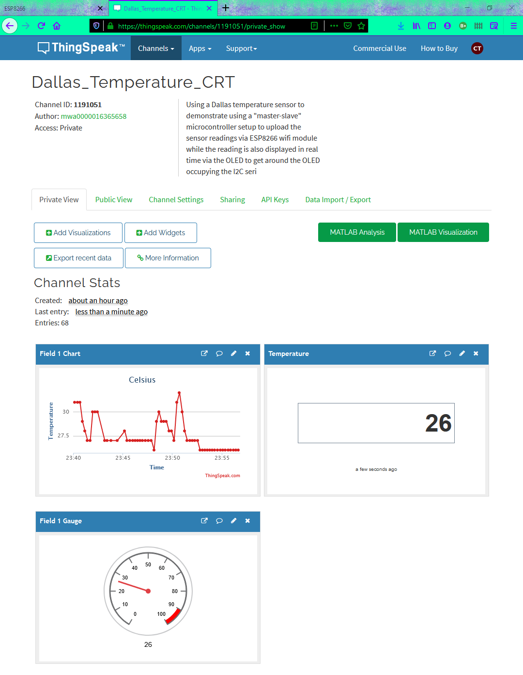
A second ATmega328P on a NANO board was introduced as another means of serial communication. This was arranged as a "master-slave" circuit to relay the data from the sensor
to the ESP so it could be uploaded to the API. In our case, the API is Thinkspeak.
The schematic of the circuit:
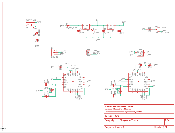
The prototype was then turned into a PCB schematic and board layout.
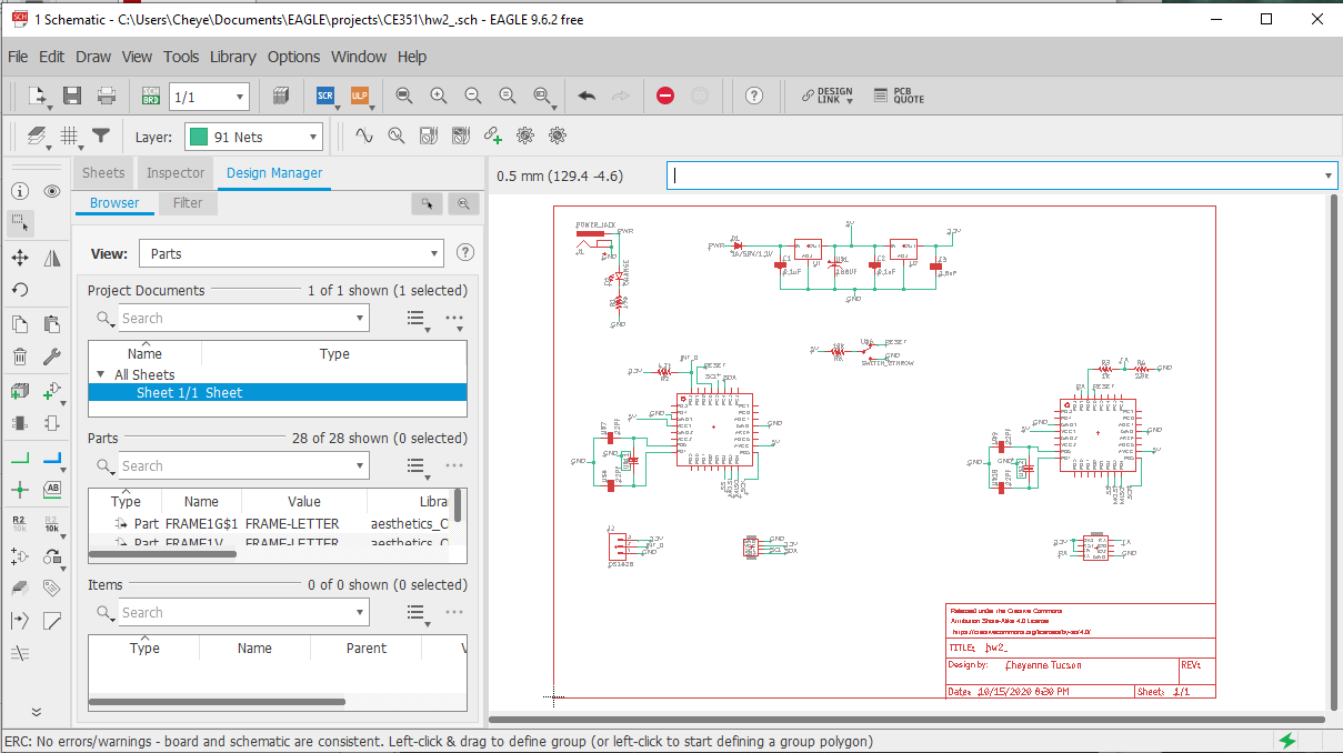
The schematic and the ERC report shown in the lower left corner:
The board layout. On the top, the bottom-view of the board and the DRC report shown in the lower left corner.
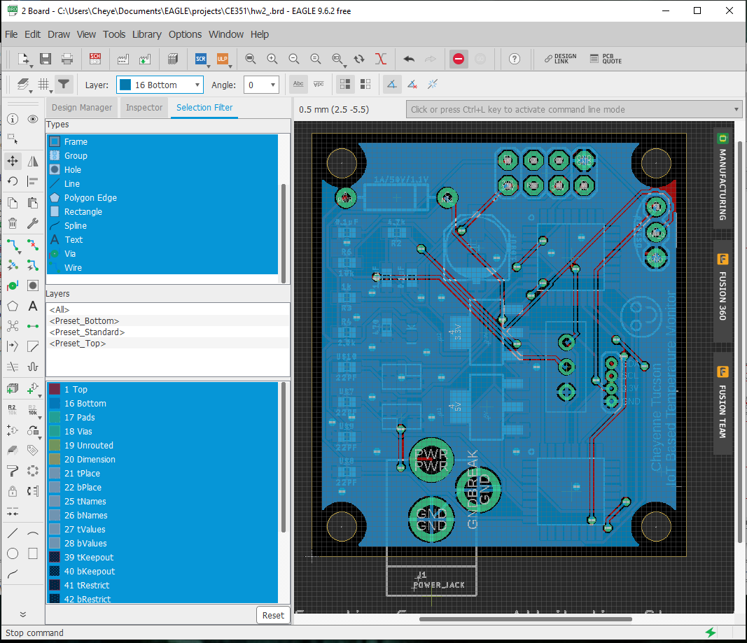
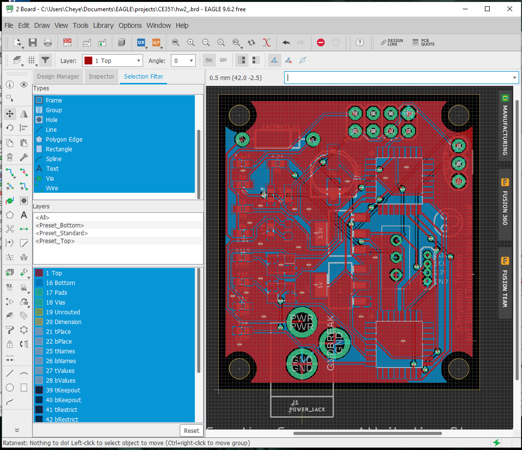 On the
bottom, the top-view of the board and the
Ratsnest report shown in the lower left corner.
On the
bottom, the top-view of the board and the
Ratsnest report shown in the lower left corner.After the PCB arrived, I soldered everything to it except for the two ATmega382 AU chips.
A picture of the PCB with all components except the ATmega 328 SMD chips can be seen in the figures below:
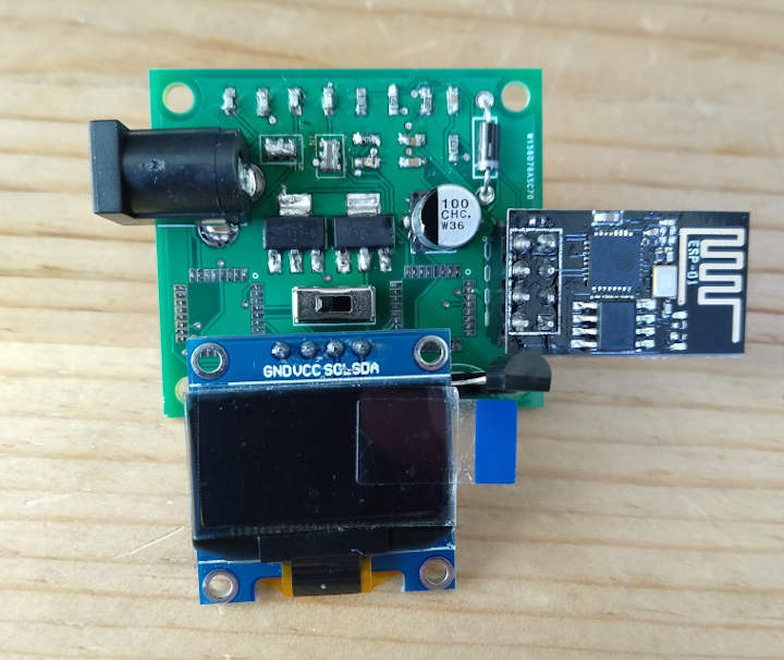
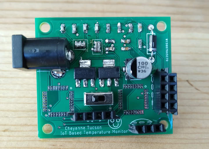
On the right is the PCB with the components in their corresponding header pins, and on the left is the PCB without the Dallas temperature sensor, the OLED, and the ESP2866 module.
I soldered an ATmega to a NANO board using a hot air soldering station and solder paste, and I tried to upload the master code. The chips were virgin and needed the bootloader burned onto the chip. Every way I tried, I would get the following error:
--------------------------------------------------------------------------
avrdude: Yikes! Invalid device signature.
Double check connections and try again, or use -F to override
this check.
--------------------------------------------------------------------------
Error while burning bootloader.
Finally after days of debugging, I figured out what was going wrong. First I changed the settings to show the verbose output when uploading, and I noticed that the signature was all 0's. This indicates that there is an issue in the circuit, and I probably used too much solder paste while attaching the chip to the NANO board. After testing for continuity with a multi-meter, it turned out that some of the pins of the ATmega were shorted together. Due to COVID-19, I wasn't able to access the hot air soldering station to correct this and try again; however, I did find a solution to this error when it is not caused by a wiring issue! It involves directly changing the device's signature in the avrdude library file. A tutorial I found suggested copying the entire arduino folder, program, etc. to a second folder, renaming it to show it's the bootloader version, and changing the avrdude library file in the bootloader version. The tutorial referenced can be found here.
4. Results