ENGR433 Spring 2023
Homework 2
Name: Cheyenne Tucson
Email: crtucson@fortlewis.edu
Data Types, Operators, and Combinational Logic
Task 1
For part a of the first task, various values in the decimal number system were converted to UQ16.16, UQ.16, and UQ15.16 number representations. This involves first converting to the binary number system with the respective number of bits in each UQ system mentioned; in this case it is 16 or 32 bits per number with 16 bit per portion (the integer part and floating point part.) This was done on paper and can be seen on Pages 1 and 2 in PDF 1.
PDF 1. This is a PDF that contains all the hand-written conversions of decimal values to fixed-point and floating-point representaions. Page 1 shows the fixed-point conversions, Page 2 shows the floating-point representation conversions, and Page 3 shows the process of floating-point addition and subtraction.
For part b of the first task, the floating-point representation of values converted from the decimal system were done by hand on paper; These can be found on Page 2 in PDF 1.
Task 2
The process of floating-point addition and subtraction was done by hand on paper. This can be found on Page 3 in PDF 1 above.
Task 3
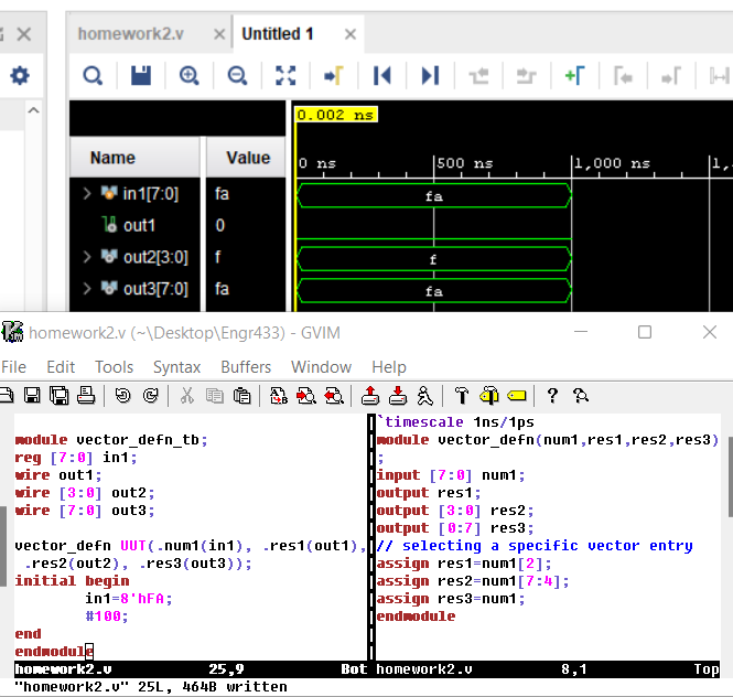
For the third task, accessing the various entries in a vector was demonstrated with Verilog and Vivado with a behavioral simulation. This can be seen below in Figure 1. Note that changing the placement of the higher value within the square brackets determines if the order is MSB or LSB first.
Figure 1. A screen-snip of the behavior simulation ran in Vivado and code demonstrating vector entry accessing with Verilog.
Task 4
Combinational logic can be implemented to achieve various objectives with some design. For Task 4, three different circuits were synthesized with a Basys3 FPGA that have real-world basic applications: a home alarm system, a combination safe, and a vacant parking-spot counter.
Demonstrations of each verilog script programmed onto the FPGA can be found in Video 1-3 below.
Video 1. A recorded demonstration of the logic for a simple 4-bit home alarm on a FPGA. Video 2. A recorded demonstration of the logic for a 4-bit digital safe implemented on a FPGA.
Video 3. A recorded demonstration of the logic for a vacant parking space counter implemented on a FPGA.