1. Introduction
Solving circuits and finding various voltage and current values withing a circuit is a crucial skill to have as an engineer who works with electronics. Using superposition and converting circuits to a Thevenin's equivalent circuit can be useful when designing circuits that have multiple voltage and current sources contributing to them. It can also be useful to figure out different ways to wire something while getting the desired result.
These techniques can help one figure out what the current and voltage potential is actually going to be in the circuit.
This is sometimes crucial to the functionality of the design. In this lab, we will practice calculating circuits using the Superposition and Thevenin's Equivalent Circuit theorems. We will confirm our calculations by simulating them in LTSpice.
3. Procedure
To begin, I reviewed how to use the superposition technique and how to convert a circuit into a Thevenin's equivalent circuit. I did so by watching the videos in the playlist found in the link above.
I also re-watched some full-length lecture videos from classes taught by Dr. Yiyan Li and Dr. Charles Hakes that I had saved on my computer from previous years at FLC.
These were recordings of classes taught in previous years that, at the time, I had to download to watch because of a poor internet connection. These recordings served to come in handy as extra practice for this lab!
I also watched some other videos I found online to review different methods of finding voltage and current values of various nodes and components as well as to follow along with example problems as they were being solved.
A pdf of notes I wrote while reviewing these topics can be found below:
The notes begin with a review of the same problems I reviewed when I took this class last Fall. The first example problem I reviewed was a circuit that does not involve superposition, and the rest of the circuits following do. The last couple of circuits are problems practicing Thevenin's equivalent theorem.
There were problems that I worked on multiple times, so there are duplicates within the notes. I also reworked the circuits in the lab by using various different methods and re-drawn circuit designs.
I then completed Task 1 by making hand calculations of the voltages and currents in the following circuit:
The original circuit is the first circuit shown in the pdf. The rest of the document is the written work for the hand calculations. Note the superimposed values of each node and component are as follows: V_A = 3V, V_B = 0.9V, V_C = 2.4V, V_D = 0V (GND), VR_1 = 2.1V, VR_2 = 0.9V, VR_3 = 2.4V, IR_1 = 1.4mA, IR_2 = 0.6mA, and IR_3 = 0.8mA.
To do this, I found all of the voltage and current values in the circuit, and I used the superposition theory to figure out the contributions from each voltage source. After the hand calculations were made, I wrote the SPICE code for the circuit to simulate and verify my calculations.
I then went to complete Task 2 by making hand calculations to find the Thevenin's equivalent of the following circuit:
The original circuit is the first circuit shown in the pdf. The Thevenin's Equivalent circuit is the last circhit shown in the document. The rest of the document is the written work for my hand calculations of R_TH and E_TH. Note that R_TH = 2kΩ and E_TH = 1.667V when the original power source is 5V.
To do this, I removed all sources and the load. There was only one voltage source in this circuit that I had to short to find R_TH. Then I calculated R_TH by combining the total resistance from looking into the circuit from the Vout end. I then added the voltage source back in to calculate the voltage at Vout. This result became E_TH. Once I found the values I needed, I redrew the circuit to the structure of a Thevenin's equivalent circuit using the E_TH and R_TH values with the original capacitor load. I then calculated the time delay, and I compared the delay from the Vin to the Vout values. After the hand calculations were made, I wrote the SPICE code for the original circuit and verify the the Thevenin's equivalent circuit I calculated by hand.
4. Results
The simulation for Task 1 produced the following results:
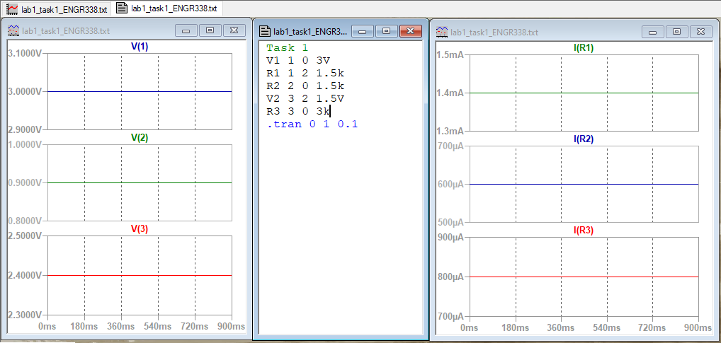
In this figure, the screensnip of the simulated circuit is shown with the plotted traces for all the voltages and currents in the original circuit.
The voltages are shown on the right, and the currents are shown on the left.
Note the voltage values at V_A at 3.0 V, V_B at 0.9 V, and V_C at 2.4 V. Also note the potential change in voltage across the resistors are VR_1 = 2.1V, VR_2 = 0.9V, VR_3 = 2.4V, and the current values flowing through each resistor are as follows: IR1 at 1.4 mA, IR2 at 0.6 mA, and IR3 at 0.8 mA.
The equivalent circuit for Task 2 produced the following results:
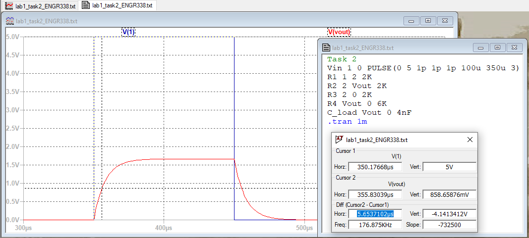
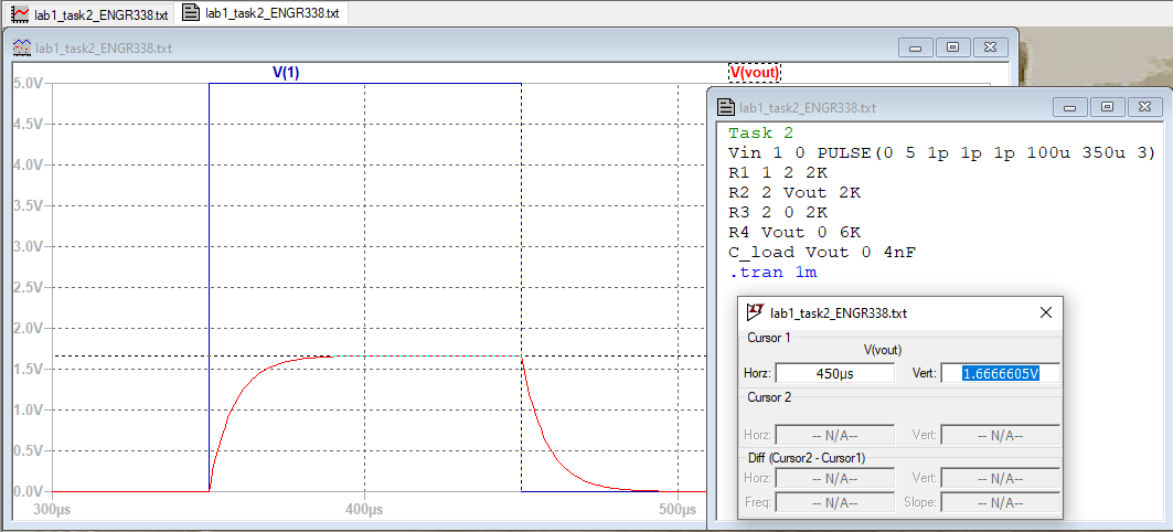
On the left is a screensnip of the time delay shown on the simulation of the original circuit. Note the value is 5.6 ms. On the right is a screensnip of the Vout of the original circuit. Note the value confirms the calculated ETH value at 1.667 V.
5. Discussion
The simulation results represented in the figure for Task 2, as seen in the Results section, match the values that I calculated by hand, as seen in the PDF for Task 2 in the Procedure section.
This applies to the figure represing the simulated circuit in Task 1 also. After reviewing superposition and Thevenin's equivalent circuit, I noticed that I am still intimidated when I first sit down and try to solve them.
When I was at home alone and relaxed, I was able to easily see what mistakes I was making in the past. I need to build my confidence in my ability to do these kind of problems, and I need to figure out why I get so anxious when I'm solving circuits in a classroom setting. All-in-all, this lab has been very good practice for me. I hope to keep getting better at solving circuits.