1. Introduction
Using buses is a convenient way to input multi-bit words into logic gates. In this lab, we will be creating a ring oscillator, and several logic gates with 8-bit buses.
Using buses is a convenient way to input multi-bit words into logic gates. In this lab, we will be creating a ring oscillator, and several logic gates with 8-bit buses.
Half-way through this lab, I unfortunately lost my library to file corruption! It was a very sad day.
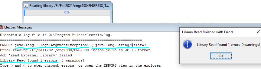
I needed to rebuild my library from Lab 2 to this present lab. This was a set-back that I needed to catch up on before proceeding again. After I became caught up again with all of my logic gates, I began by creating a shorter version on the 20/10 Inverter from Lab 5. I did this by shortening the distance of the p-well and n-well from their respective transistors. I used this inverter in a new schematic to create a ring oscillator with the array tool. Once the schematic came back DRC clean, I ran a simulation in LTSpice. Next, I repeated this process with using a 10-bit bus instead of using the array tool. After this came back clean on all checks, I ran another simulation, and then I created the layout view.
I repeated this process for the following logic gates: the AND gate, the OR gate, the NAND gate, and the NOR gate. All of the screen-snips of these steps can be found in the PDF in the Results section. In the layout view, you cannot just wire a whole bus as the input because it would short all of the input signals together, and every gate would be sent the same input. To account for this, I had to make each input a metal-2 node to be able to access each bit of the bus.
I learned a very valuable lesson about backing up your files. Unexpected things can happen, and precious files can be lost in an instant. This forced me to put in extra practice with these skills. At least the set-back proved to be useful in this way. I am much more confident in my ability to layout different features in Electric.