CE433 2023 Spring
Report 4: Data Storage Units
Name: Vann Montoya
Email: bvmontoya@fortlewis.edu
Data Storage Units
Introduction:
The purpose of this assignment is to introduce logic data storage units.
Materials and Methods:
gVim
Vivado
Basys 3 board
Results
1. Repeat the simulation in Sections 1 - 3. (20 points)
Section 1: SR Latch/Flip-Flop
SR Latch
Here is the code for the SR Latch module and test bench:
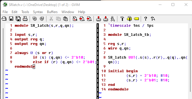
Figure 1: SR Latch Code module and test bench.
Here are the results from the simulation:
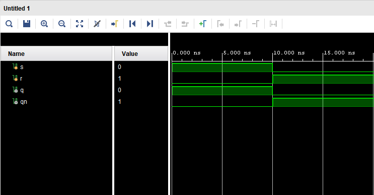
Figure 2: SR Latch simulation results.
Flip-Flop
Here's the code for the SR Flip-Flop module and test bench:
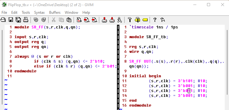
Figure 3: SR Flip-Flop module and test bench code.
Here are the results from the simulation:
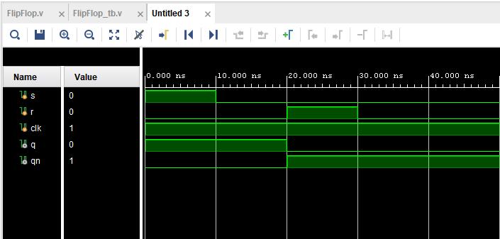
Figure 4: Results from the SR Flip-Flop simulation.
Section 2: D-Latch
Here is the code for the D-Latch module and test bench:
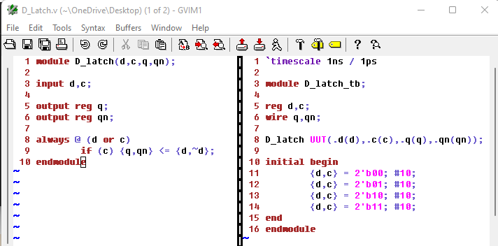
Figure 5: Code for the D-Latch module and test bench.
Here are the results from the D-Latch simulation:
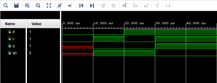
Figure 6: Results from the D-Latch simulation.
Section 3: Edge Triggered D-Flip-Flop
Here's the code for the D-Flip-Flop module and test bench:
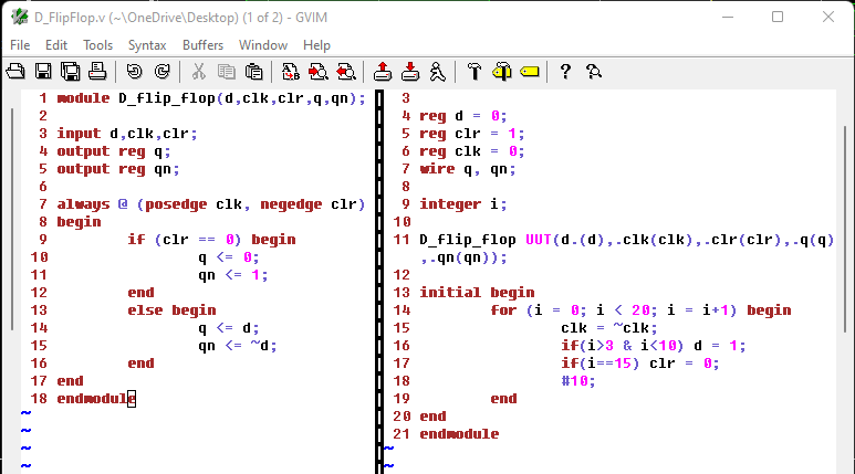
Figure 7: Code for the D-Flip-Flop module and test bench.
Here are the results from the simulation:
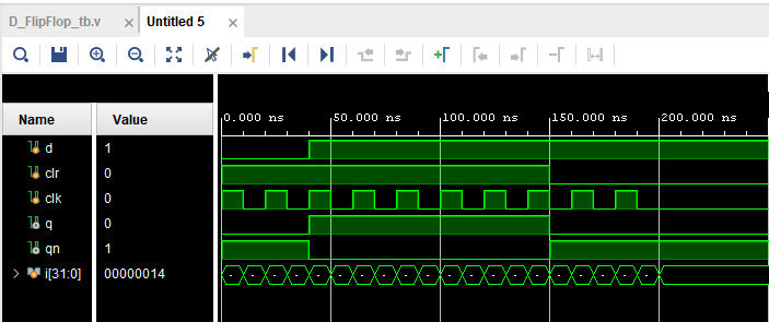
Figure 8: Results from the D-Flip-Flop simulation.
2. Write the testbenches and run simulations for Section 4 and Section 5. (20 points)
Section 4: JK Flip-Flop
Here's the code for the JK-Flip-Flop module and test bench:
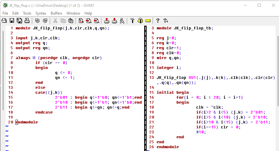
Figure 9: Code for the JK-Flip-Flop module and test bench.
Here is the results from the simulation:
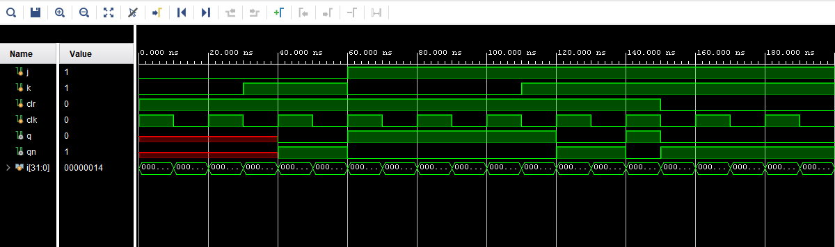
Figure 10: Results from the JK-Flip-Flop simulation.
Section 5: T-Flip-Flop
Here's the code for T-Flip-Flop module and test bench:
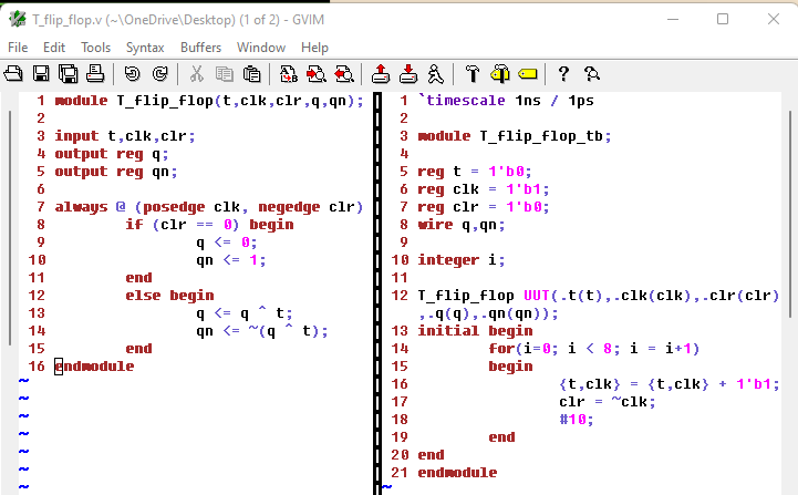
Figure 11: Code for the T-Flip-FLop module and test bench.
Here are the results from the simulation:
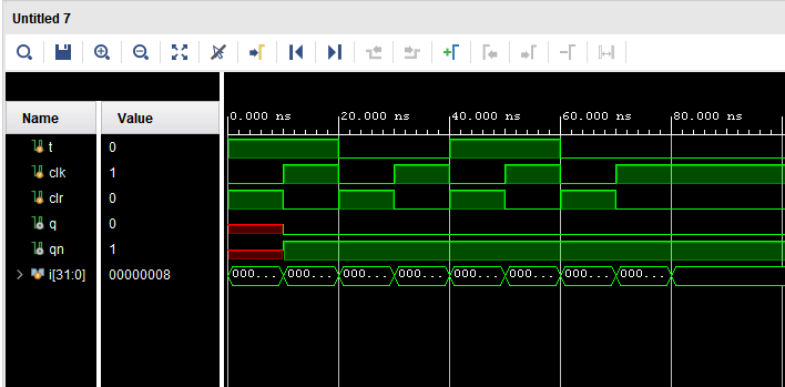
Figure 12: Simulation results for the T-Flip-Flop.
3. Repeat all the work in Section 8 and complete the task described in the end of Section 8. (60 points)
ROM 8-bit Binary:
Here is the code for the module and test bench:
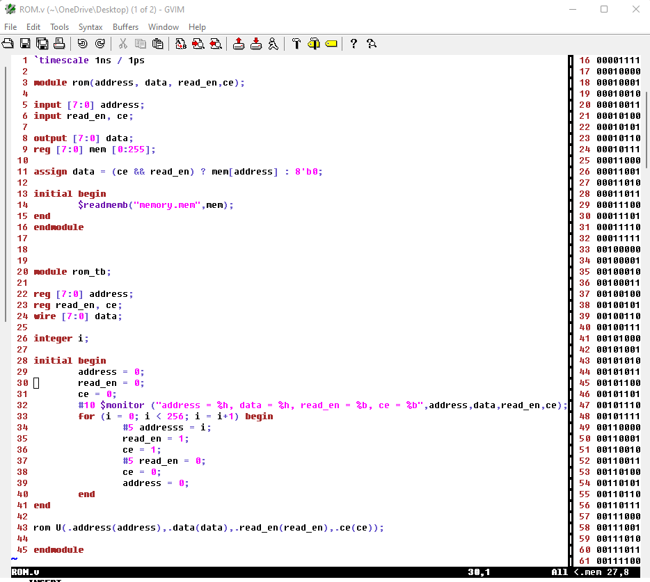
Figure 13: Code for the ROM 8-Bit Binary module, test bench and memory .mem file.
Here are the results from the simulation:
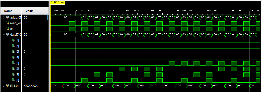
Figure 14: Results from the ROM 8-Bit Binary simulation.
ROM 4-Bit Hex:
Here's the code for the ROM 4-Bit Hex module, test bench and mem file:
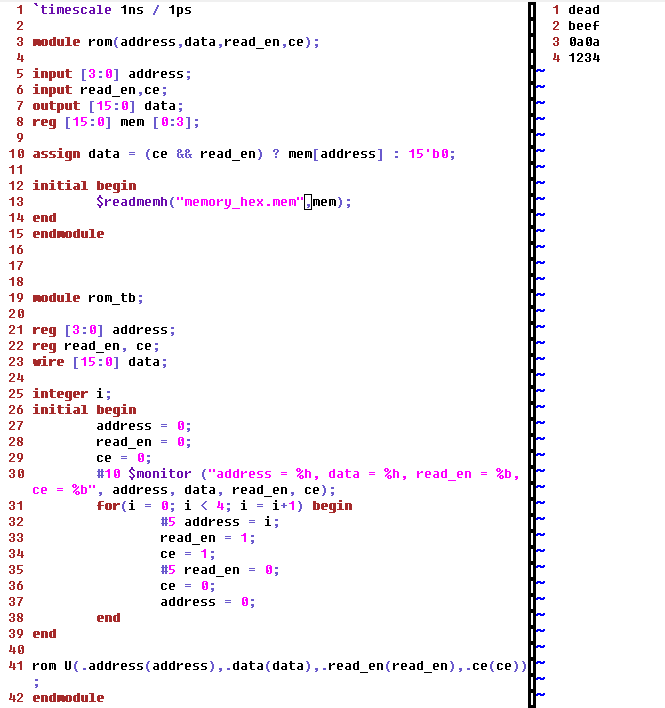
Figure 15: ROM 4-Bit Hex module and test bench code.
Here are the results from the ROM 4-Bit Hex simulation:
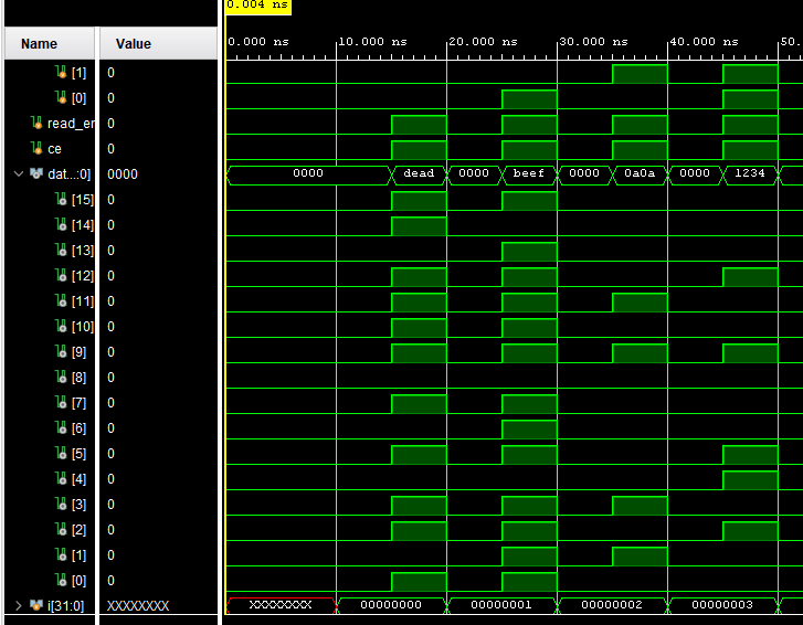
Figure 16: Simulation results from the ROM 4-Bit Hex simulation.
ROM 8-Bit Hex:
Here's the code for the ROM 8-Bit Hex module, test bench and .mem file:
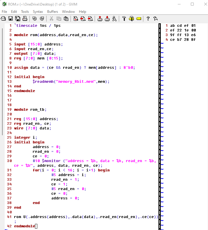
Figure 17: ROM 8-Bit Hex module, test bench and .mem file.
Here are the results from the ROM 8-Bit Hex simulation:
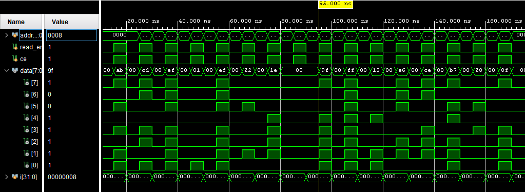
Figure 18: ROM 8-Bit Hex simulation results.
ROM 3-Bit Binary:
Here's the code for the ROM 3-Bit Binary module, test bench and .mem file:
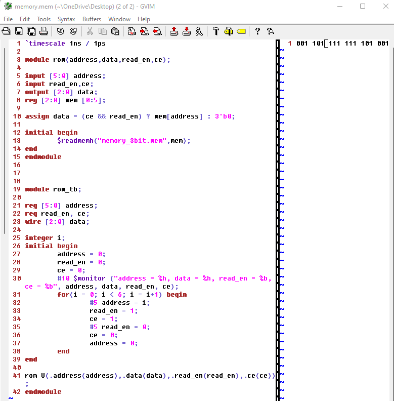
Figure 19: Code for the ROM 3-Bit Binary module, test bench and .mem file.
Here are the results for the ROM 3-Bit Binary simulation:
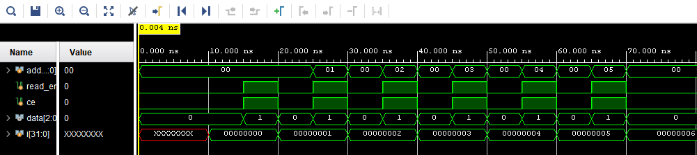
Figure 20: Results from the ROM 3-Bit Binary simulation.