CE 433-2 2023 Spring
Report 2: Data Types, Operators, and Combinational Logic
Name: Vann Montoya
Email: bvmontoya@fortlewis.edu
Data Types, Operators and Combinational Logic
Introduction
This assign is to introduce fixed and floating point representations of decimals and how to convert to them.
Then introduces simple applications for programming the FPGA.
Materials and Methods
gVim
Vivado
FPGA
Results
Tasks
Task 1. Work on the following problems: (40 points)
a. What are the fixed point representations of the following decimal numbers?
20.25 in UQ16.16 = 0014.4000
First convert to binary:
0000 0000 0001 0100.0100 0000 0000 0000
Then convert each segment to hex:
0014.4000
128.5 in UQ16.16 = 0080.8000
Convert to binary:
0000 0000 1000 0000.1000 0000 0000 0000
Then convert each segment to hex:
0080.8000
0.125 in UQ.16 = .2000
Convert to binary:
0000 0000 0000 0000.0010 0000 0000 0000
Then convert each segment to hex:
0000.2000
Cut off the integer:
.2000
-38.125 in UQ15.16 = 8026.2000
Convert to 15-bit binary with a "negative" infront:
1000 0000 0010 0110.0010 0000 0000 0000
Then convert each segment to hex:
8026.2000
-50.0625 in UQ15.16 = 8032.1000
Convert to 15-bit binary with a "negative" infront:
1000 0000 0011 0010.0001 0000 0000 0000
Then convert each segement to hex:
8032.1000
b. What are the floating point representations of the following decimal numbers?
0.141 in half precision/format = 3083
Convert to binary:
0.00100100000110001001 = 1.00100000110001001*2^(-3)
S = 0 (b/c positive)
E = 15 + (-3) = 12
Convert 12 to binary:
12 = 01100
Everything after the binary point for 10-bits:
F = 0010000011
Now construct X = SEF
x = 0 01100 0010000011
Lastly convert each segment to hex:
x = 0011 0000 1000 0011
x = 3083
3.625 in half precision/format = 4680
Convert to binary:
11.101 = 1.1101 * 2^(1)
S = 0 (b/c positive)
E = 15 + 1 = 16
Convert 16 to binary:
16 = 10000
Everything after the binary point for 10-bits:
F = 1101 000000
Now construct X = SEF:
x = 0 10000 1101 000000
Lastly convert each segment to hex:
x = 0100 0110 1000 0000
x = 4680
-15.25 in half precision/format = D280
Convert to binary:
1101.1 = 1.101^2(3)
S = 1 (b/c negative)
E = 15 + 3 = 18
Convert 18 to binary:
18 = 10100
Everything after the binary point for 10-bits:
F = 101 0000000
Now construct X = SEF
x = 1 10100 101 0000000
Lastly convert each segment to hex:
1101 0010 1000 0000
x = D280
Task 2. Show the process of floating point addtion/subtraction of the following operations. (20 points)
a. 15.25 + 4.125 = 19.375
First convert:
15.25 = 1111.01 = 1.11101*2^(3)
Then the second:
4.125 = 100.001 = 0.100001*2^(3)
Now add:
(1.111010 + 0.100001)*2(3) = 10.011011^(3)
Convert back:
10.011011^(3) = 10011.011 = 19.375
b. 15.25 - 4.125
First convert:
15.25 = 1111.1 = 1.111*2^(3)
Then the second:
-4.125 = 1100.001 = 1.100001*2^(3)
Now add:
(1.111000 + 1.100001)*2^(3) = 100.011001*2^(3)
Task 3. Repeat the simulation work in Section 11. (20 points)
Section 11 had code snippet, which I wrote into Vivado and ran the simulation.
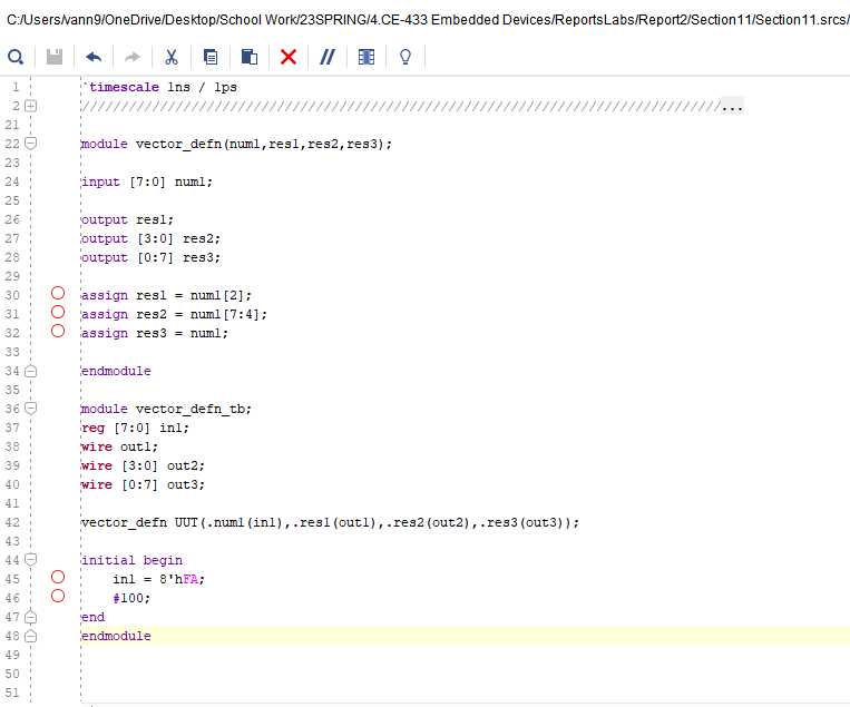
Figure 1: Code used for this section.
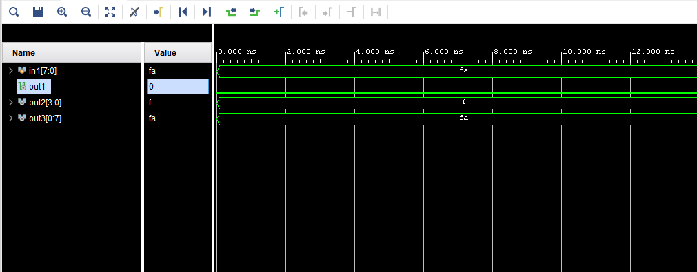
Figure 2: Simulation results.
Task 4. Repeat the work in Section 14.1, 14.2, and 14.3. (20 points)
Section 14.1 - Home Alarm
Section 14.1 is to make a simple home alarm system based on this logic:
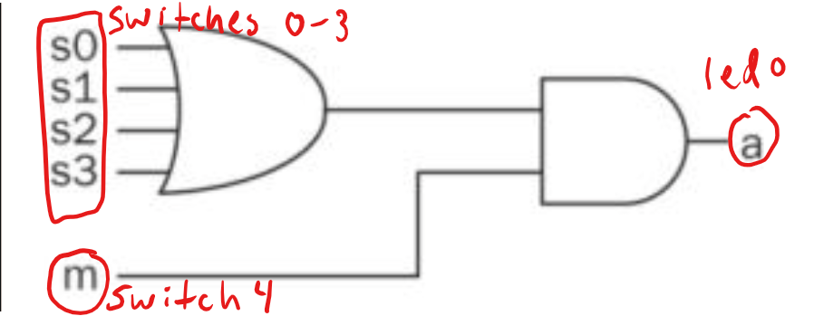
Figure 3: Simple home alarm system based on 5 switches and an led for output.
Switches 0 to 3 will act as 'tripping' points for the system and switch
4 will be used as an 'arming' switch to turn the system on an off.
So anytime that switch 4 is 'armed', if any of the other switches are 'tripped' then the led will alert.
Here is the code and test bench for programming the FPGA:
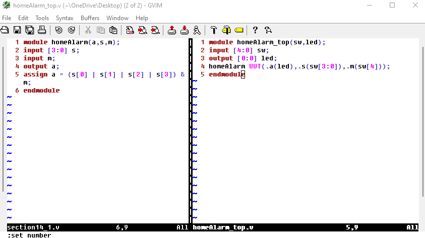
Figure 4: Code for the home alarm.
The code was then used to program the FPGA.
Here is a Youtube link showcasing the logic: Youtube Link
Section 14.2 - Digital Safe System
This is designed to mimic a simple password system using the switches to match a pre-defined 'password' of bits.
For an example, switches 0-3 will be used where each switch represents
a bit and say we had a 4-bit password of 0101, then switches 3 and 1
would need to be toggled to 'unlock' the password.
Here is the logic behind the password system:
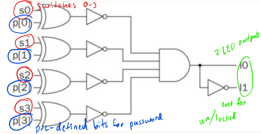
Figure 5: Simple logic for the password system.
XOR gates are used with the bits of the password and the state of the
switches because they could determine whether they match regardless if
it were both 0's or 1's.
Then they are all connected with an AND gate to make sure all the switches match their respective bits.
There are two leds for output. One is for showing that the system is still 'locked' and another for 'unlocked'.
Here is the code for the password system:
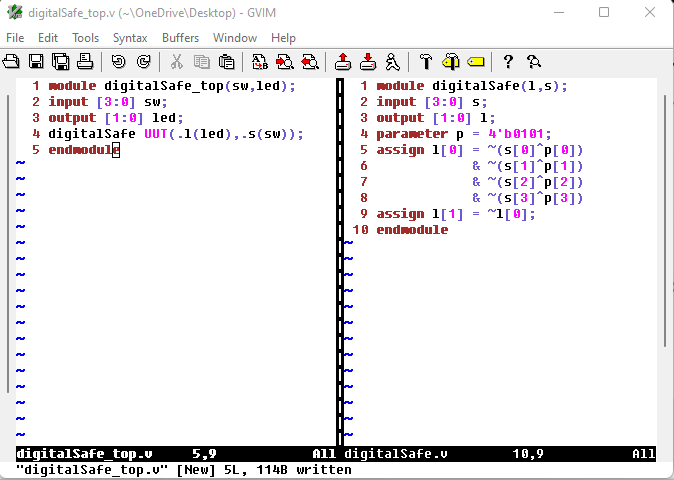
Figure 6: Code used for the password system.
In the code, the password has been set to 0101 meaning that switches 0 and 2 would need to be toggled to match the password.
In the Youtube video, you can see that led 1 is lit indicating that it is 'locked' but once switches 0 and 2 are switched on,
then led 0 lights and led 1 turns off indicating a correct password has been entered.
Section 14.3 - Car parking occupancy counting system
Imagine there is a parking lot with three parking spots each with sensors to determine if they are occupied.
Represent each of the parking spots as S_0, S_1, and S_2, and each occupied spot is counted.
We can represent this in a truth table:
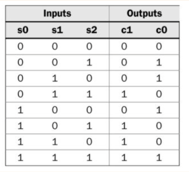
Figure 7: Truth table for counting occupied spots.
As you can see, any time a single spot is taken, C_1 = 0 and C_0 = 1 (01) representing one spot occupied.
Anytime two spots are occupied, then we get C_1 = 1 and C_0 = 0 (10) representing two spots are occupied.
When all three spots are occupied, then both C_1 and C_0 are 1 (11) representing all three spots are occupied.
Now we can build the logic from this truth table:
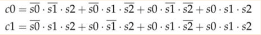
Figure 8: Logic from the truth table.
Now we can code the logic:
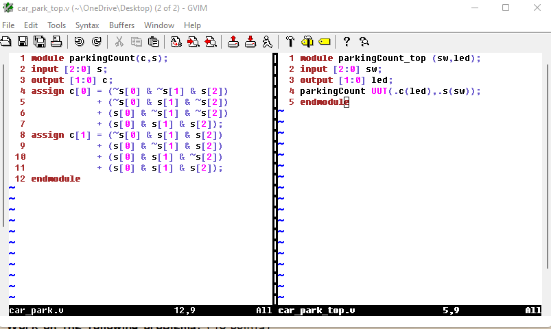
Figure 9: Code for the parking space counter.
From the Youtube video you can see that anytime a single switch is toggled, led 0 = 1. (01)
Anytime two switches are toggled, led 1 = 1 and led 0 = 0 (10)
And when all three switches are toggled, led 1 = 1 and led 0 = 1 (11)