CE 433-2 2023 Spring
Report 1: Verilog and FPGA Basics
Name: Vann Montoya
Email: bvmontoya@fortlewis.edu
Verilog and FPGA
Basics
Introduction
The purpose of this assignment is to help learn the basics of Verilog and FPGAs through examples.
Materials and Methods
gVim
Vivado
Results
Task 1:
Use gvim and Vivado to simulate the examples in sections 2.1, 2.2, and
2.3. Post snapshots of gvim windows and vivado simulation results in
your report. You must create testbenches for your simulations. (20
points)
For the following sections 2.1, 2.2, and 2.3, the same test bench script was used for each:
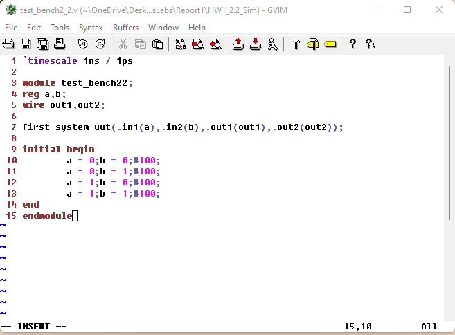
Figure 1: A screenshot of the test bench script used for sections 2.1, 2.2, and 2.3.
Section 2.1 - Structural Modeling
Here is the script used for section 2.1 demonstrating the structural modeling method.
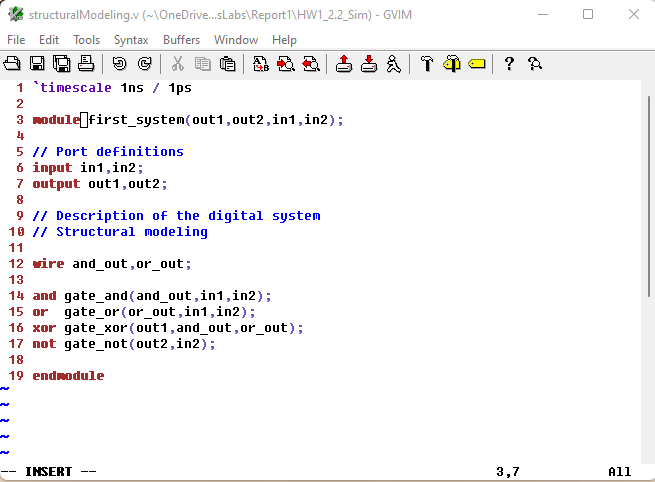
Figure 2: A screenshot of the script used to demonstrate the structural modeling method that was written with gVim.
Here is the simulation results from the structural modeling script:
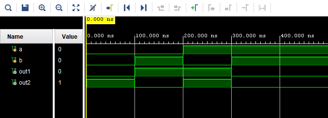
Figure 3: A screenshot showing the results of the structural modeling script.
Section 2.2 - Dataflowing Model
Here is the script used to demonstrate the dataflowing model written with gVim.
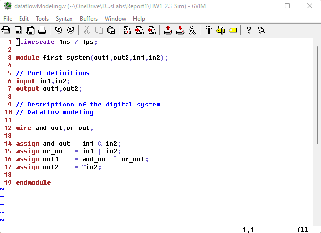
Figure 4: A screenshot of the script used to demonstrate the dataflow model
Here is the results of the dataflow model script and test bench:
Figure 5: A screenshot showing the results of the dataflow model method.
Section 2.3 - Behavioral Model
Here is the script used to demonstrate the behavioral model:
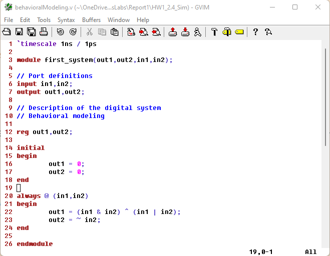
Figure 6: A screenshot of the script used to demonstrate the behavioral model method.
Here is the results of the behavior model script and test bench:
Figure 7: A screenshot showing the results of the behavioral model method.
Task 2: Run a simulation to show the difference between blocking and non-blocking assignment in the example in section 2.4. (20 points)
Here is the blocking and non-blocking assignment created using gVim.
You can see within the always statement the blocking (=) and non-blocking assignments (<=).
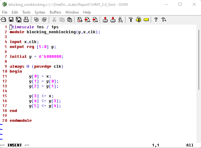
Figure 8: A screenshot of the blocking and non-blocking module.
Here is the test bench created to demonstrate the blocking and non-blocking.
The clock is meant to alternate very 10 nano seconds to help demonstrate blocking assignment.

Figure 9: A screenshot of the test bench used for the blocking and non-blocking assignment module.
Here are the results from the simulation.
As you can see, y[0:2] have been immediately assigned values due to the blocking assignment.
0 -> x -> y[0] -> y[1] -> y[2]
Whereas, y[3:5], staggered the assignment.
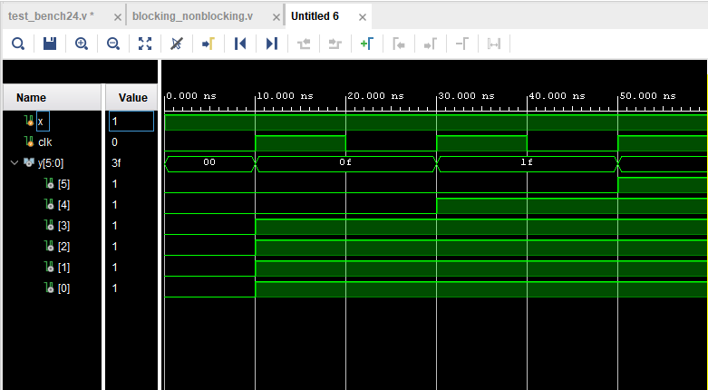
Figure 10: A screenshot of the blocking and non-blocking assignment simulation results.
Task 3: Repeat the simulation example in section 2.5. (20 points)
Here is the delay module written for this simulation.
Notice the 20 nano second delay added on line 9.
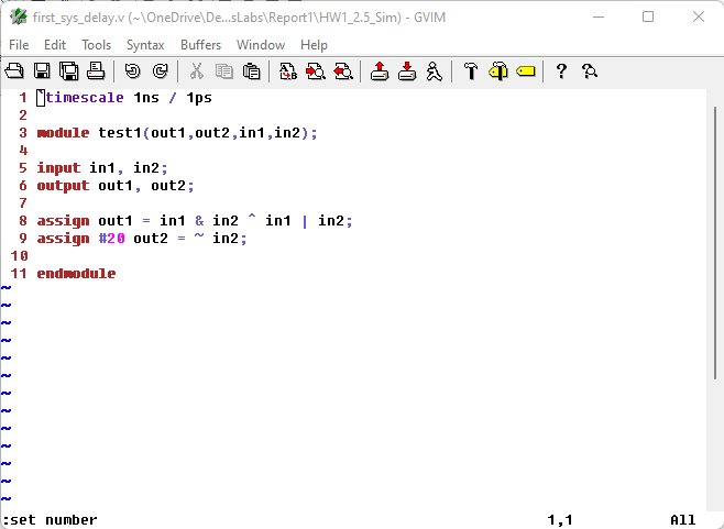
Figure 11: A screenshot of the delay module.
Here is the test bench written for this simulation. This will be the same test bench for this task and task 4.
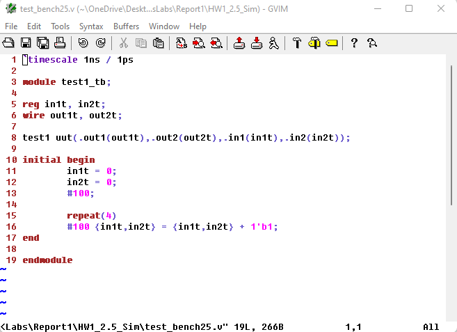
Figure 12: A screenshot of the test bench module.
Here are the results from the simulation.
Notice the initial 20 nano second delay on out2t.
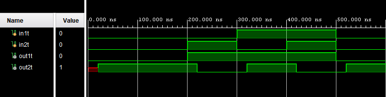
Figure 13: A screenshot of the results from the delay simulation.
Task 4:
For the example in section 2.5, move the 20 ns delay from Line [9] to
Line [8] and run the simulation. Then hand draw the timing diagram. (20
points)
Here is the script with the delay swapped from line 9 to line 8.
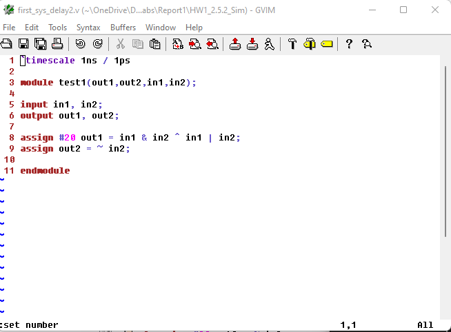
Figure 14: A screen shot of the updated delay script.
Here are the results of the new delay.
As you can see, the delay is now on out1t instead of out2t.
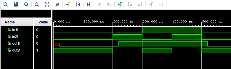
Figure 15: A screen shot of the updated simulation results.
Here is the timing diagram for the updated delay.
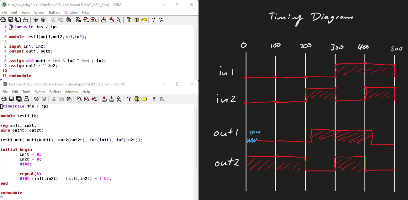
Figure 16: A screen shot of the hand drawn timing diagram.
Task 5:
Use gvim and vivado, repeat the example in section 2.6. Post the gvim
windows and the vivado simulation windows for credit. (20 points)
Here is the script used for multi-module logic.
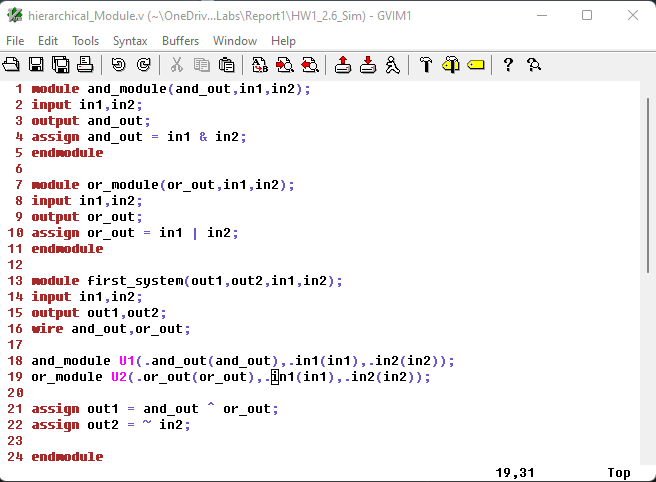
Figure 17: A screen shot of the hierarchical module script.
Here is the test bench used for the hierarchical module script.
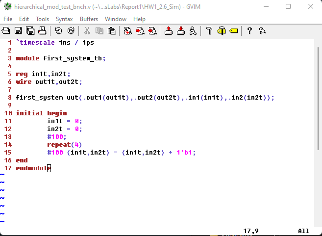
Figure 18: A screen shot of the test bench for this simulation.
Here is the results from the simulation.
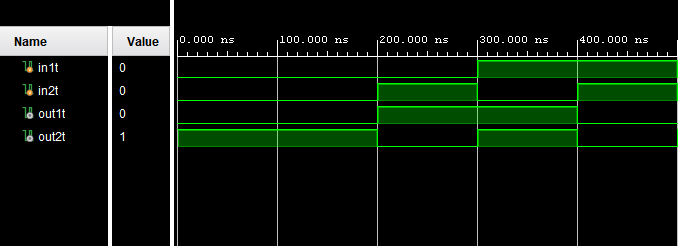
Figure 19: A screen shot of the results from the simulation.
Discussion
This assignment really helped me understand and practice creating modules and test benches.