Designing a Power Module PCB
Introduction
The purpose of this assignment was to design and create a PCB board for a basic power supply to be used for future projects.
The board needed to be able to supply four modes of power: 5V at 1A, 3.3V at 1A, 5V at 3A, and 3.3V at 3A.
The schematic and PCB board will be created using Eagle, a PCB board desiging software.
Materials and Methods
Eagle
Results
First was to make sure all the components that will be used were available in Eagle.
Majority of the components needed were already existed in the library whereas some needed to be created.
This included creating the devices' footprint and symbols.
Some of the devices created include capacitors, diodes, and switches.
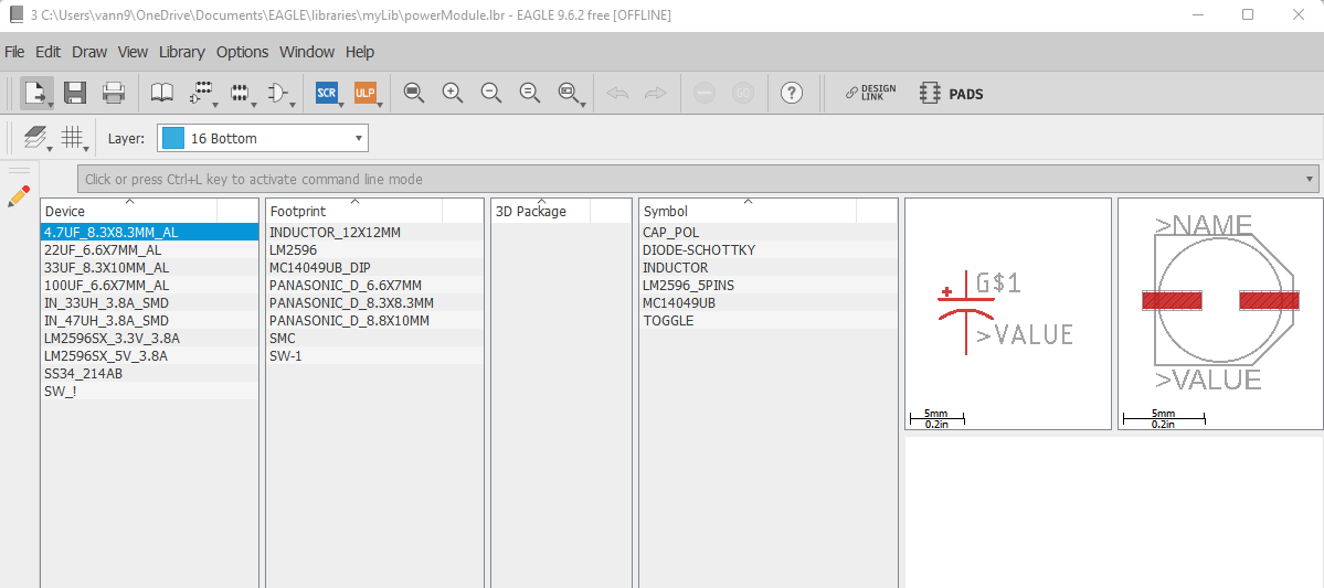
Figure 1: A screenshot showing some of the devices created for this project showcasing an 4.7uF aluminum capacitor.
Next was to create the schematic using all the components.
The board will be controlled with four switches. One acting as the main on/off switch, and the other three to toggle between the different power modes.
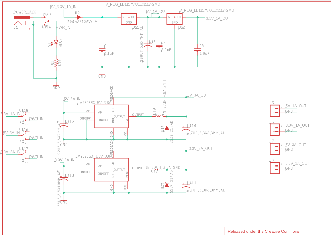
Figure 2: A screenshot of the schematic created for this project.
Once the schematic was completed, the PCB board was created.
Next was to layout all the components of the board and route the traces.
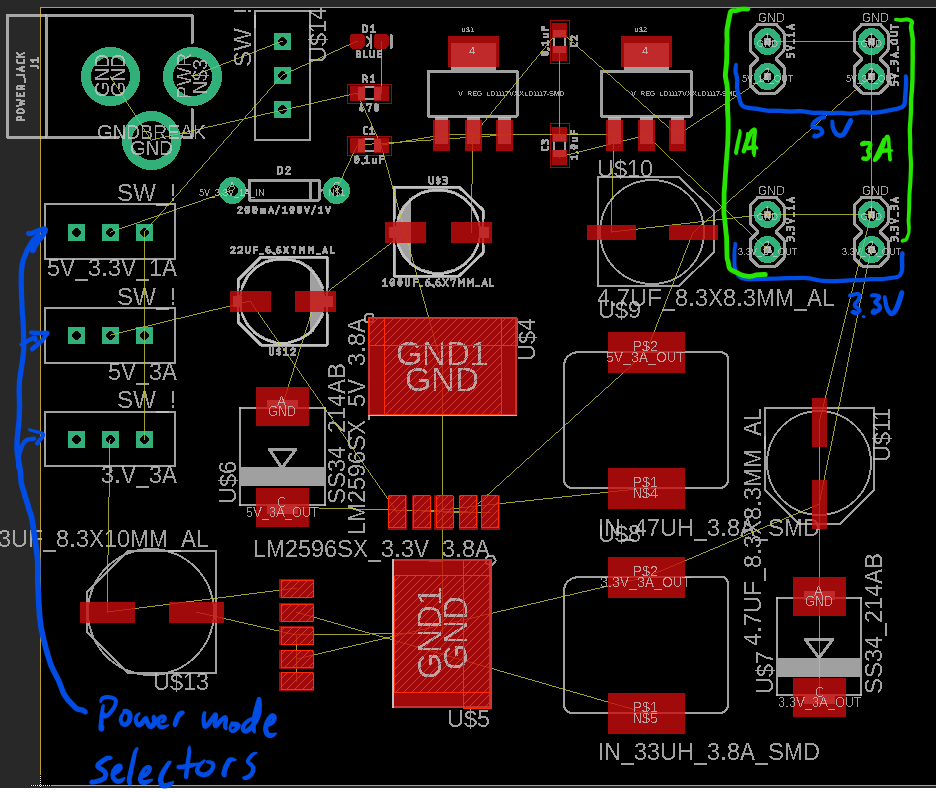
Figure 3: PCB board component layout.
I've designed the board to have pin-outs for delivering the different power modes. The intention was to have the board next to breadboard projects and deliver power via M-F jumper wires.
Next was to route the traces connecting each component.
Red represents top layer traces and blue for bottom layer.
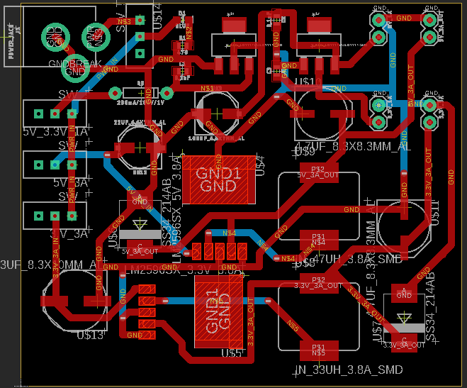
Figure 4: PCB layout showing connecting traces.
Here is the fabricated PCB board:
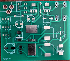
Figure 5: Fabricated PCB board.
Now to solder the components and test. As you can see below, power is connected and the board does turn on.
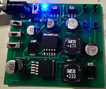
Figure 6: The board soldered and tested.
Now to test the 5V and 3.3V.
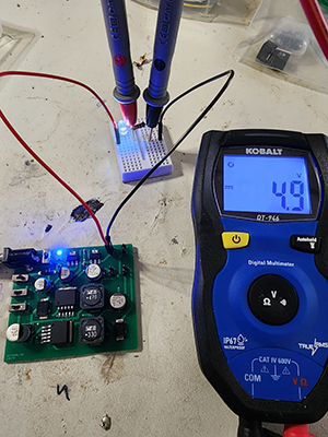
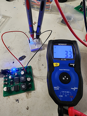
Figure 7: Here you can see the multimeter showing ~5V and 3.3V.