CE351 2023 Spring
LCDs, Sensors, and Actuators
Name: Vann Montoya Email: bvmontoya@fortlewis.edu
LCDs, Sensors, and
Actuators
Introduction
The purpose of this assign is to:
Goals:
1. Be able to use LCD as the display device
2. Be able to use temperature, humidity, untrasonic, and remote sensors
3. Be able to use motors as actuators
Materials and Methods
Arduino Uno
LCD1602 Display Module
Thermistor
DHT11 temperature and humidity sensor
IR Receiver Module
IR Remote
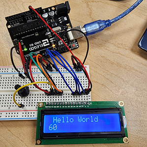
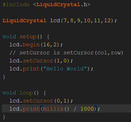
Results Tasks: Task 1:Display the 'Hello World!' starting from the second rectangle on the same lines.
Figure 1: Hello World code with the cursor set to the second column of the first row when printing "Hello World".
Figure 2: Arduino and LCD displaying "Hello World" and a counter since the device turned on.
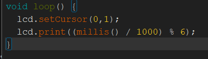
Task 2:Count to 5 and then reset to 0, then start over:
For this task, I will be re-using the Hello World program from the
first task and only modifying a single line. In
order to make the counter count up to 5 then reset, I've added a
modulus operator to the counter so that way it would count up to 5 and
reset.
Figure 3: The loop of the "Hello World" program has been changed to print the seconds modulo 6.
Here is aYoutube video demonstrating the counting function:
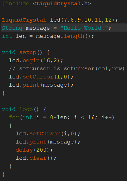
Task 3:Given
that the command 'lcd.clear()' will clear out everything on the LCD.
Modify the code to implement the scrolling text as presented in the
video below:
For this task, I use a for loop to shift the cursor from the first position to the last position.
Figure 4: LCD scrolling text code.
Here's the Youtube video displaying the scrolling message:
Task 4:Repeat the work above, show room temperature on the LCD. Use your finger to warm it up see if it changes
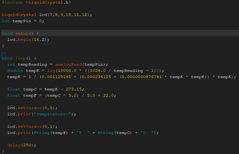
This task uses the simple thermistor to measure the temperature.
Figure 5: Code for the thermistor.
Here's a Youtube video demonstrating the temperature read out from the thermistor on the LCD:
Task 5:Modify
the code to display in the form below. Simply blow at the sensor to
change the temperature and the humidity to test it. Show a
demonstration video in your report.
I've modified this code to display both Celsius and
Fahrenheit on the LCD. It toggles between both after a few seconds.
Figure 6: Code for the DHT11 temperature and humidity module sensor.
Here's a Youtube video demonstrating the DHT11 Temperature and Humidity Sensor:
Task 6:Repeat the work above to display temperature data from TMP36.
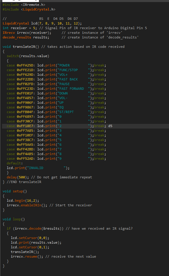
Task 7:Modify the example code to match your new remote controller. (The example code). You do not have the datasheet for the new remote controller available.
The way to decode it is to just press every button on the new remote
controller and look at the response on the LCD. Just map the code for the key to the actual function assigned/printed on the key on the remote controller.
Here's the code for the IR receiver: Figure 7: Code for the IR receiver.
Here's a Youtube video demonstrating the IR receiver and remote:
Task 8:Repeat the work in the demo video above, show your result in a VIDEO for the report.
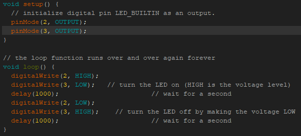
For this task, we are running the ATMEGA 328P chip standalone on the breadboard.
For demonstration purposes, I'm using a very simple LED Blink program uploaded to the chip.
. Figure 8: Simple blink LED program.
Here's a Youtube video demonstrating the functionality of the Arduino:
Task 9:Use
the barebone ATMega 328p to build a portable digital temperature meter.
Use an Interrupt Service Routine to update the temperature display.
The temperature/humidity sensor is the DHT11, the display unit is the 4-digit 7-segment display. Record a video for the report.

 .
.