CE351 2023 Spring
Heart Rate and Blood Oxygen Saturation Monitor
Name: Vann Montoya Email:
bvmontoya@fortlewis.edu
Heart Rate
and Blood Oxygen Saturation Monitor
Introduction
The purpose of this assignment is to create a heart rate and blood
oxygen monitor using Arduino and a MAX30102 Pulse Oximeter and Heart
Rate Sensor.
Materials and Methods
Arduino
MAX30102 Pulse Oximeter and Heart Rate Sensor
Breadboard
Jumper wires
OLED display
Results Tasks:
Task 1. Show
the following results (week
1, 20 points)
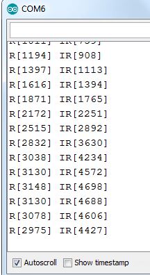
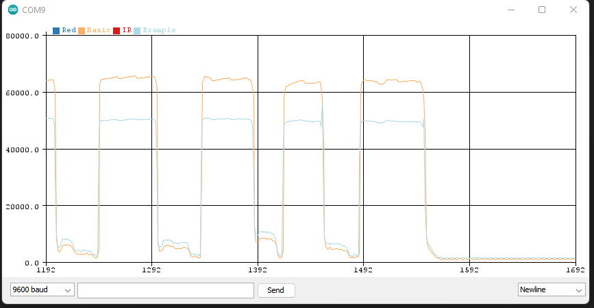
- Red and IR lights in the serial monitor.
We are wanting to reproduce the
following readings from the Arduino and the pulse oximeter and heart
rate sensor:
Figure
1: Example of the red and IR readings.
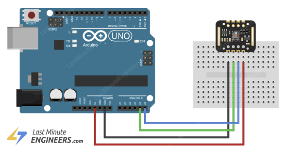
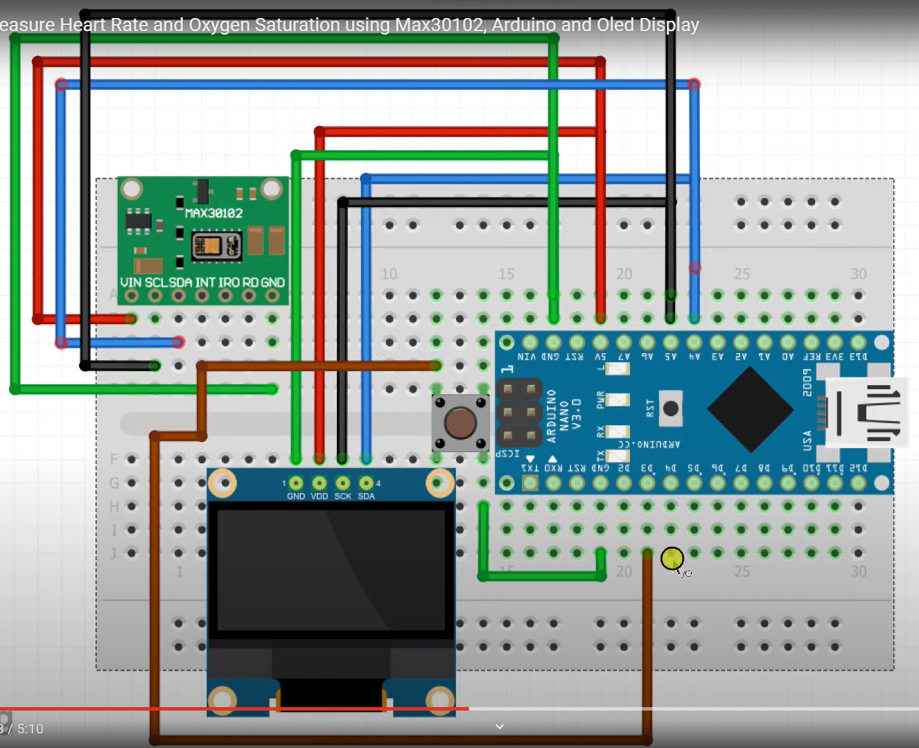
After having wired the Arduino and
heart rate sensor based on this wiring schematic:
Figure
2: Arduino and pulse oximeter and heart rate sensor wiring
diagram.
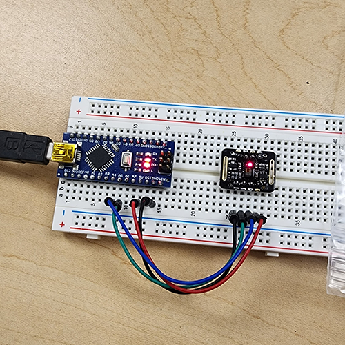
Figure
3: Arduino and pulse oximeter and heart rate sensor wired using
a breadboard.
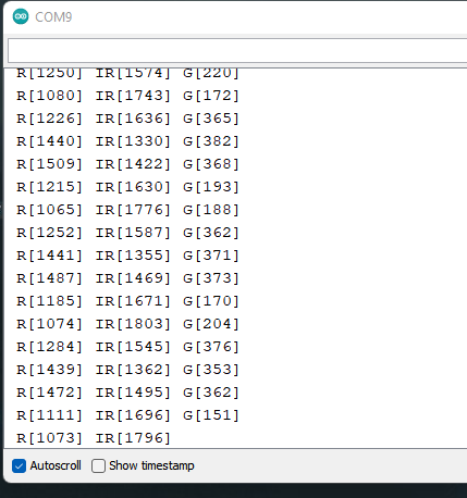
Gave the following readings from the
serial monitor:
Figure
4: Red, Green and IR readings from the Arduino.
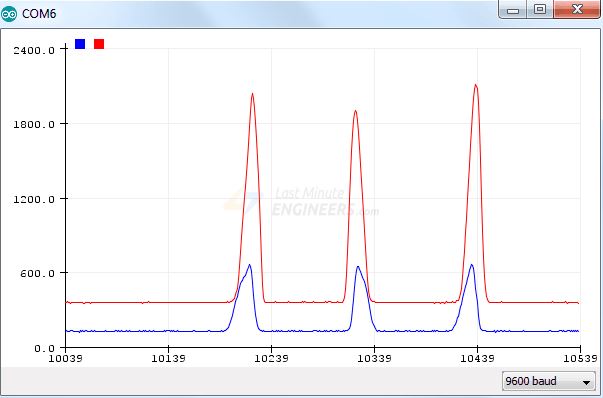
- Red and IR reading in the serial plotter.
Now we want to plot the readings
instead like so:
Figure 5: Red
and IR readings plotted example.
Using the same set up as previous, the
red and IR reading values have been plotted using the serial plotter:
Figure
6: Red and IR readings plotted.
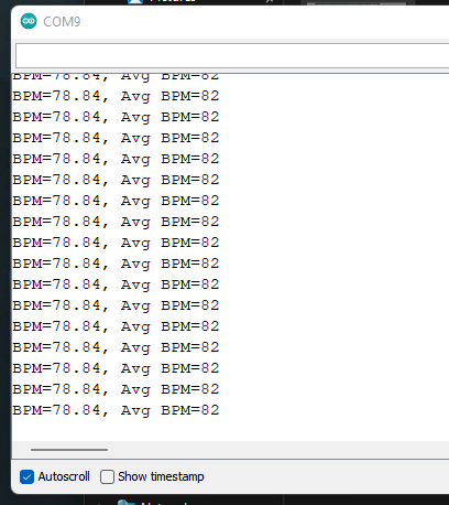
- Measure heart rate (BPM) in serial monitor.
Using the same layout and wiring but
different code, we can produce a heart rate reading in beats per minute
(BMP) in the serial monitor.
Figure
7: Serial monitor showing heart rate in BPM.
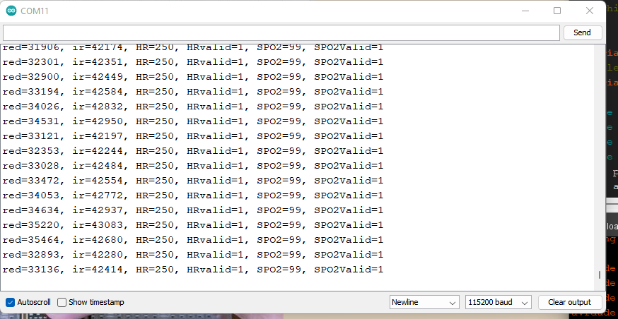
- Measure Oxygen Saturation (SpO2) in serial monitor.
Now to measure oxygen saturation (SpO2)
in the serial monitor.
Same set up as previous measurements,
only difference is the code uploaded to the Arduino.
Figure
8: SpO2 measurements in the serial monitor.
Task 2. Display
Pulse Rate and Oxygen Saturation on OLED display (week 1, 20
points)
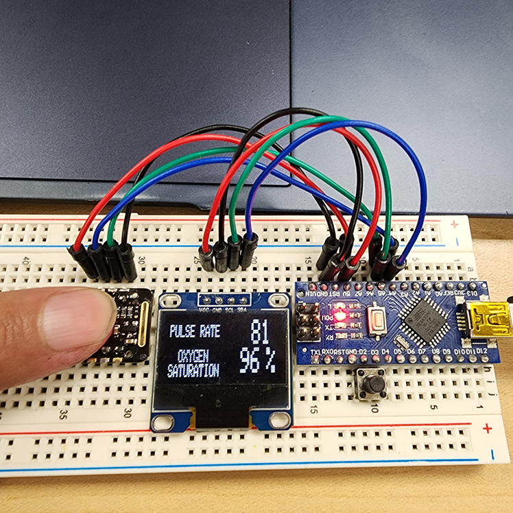
Now we want to add an OLED display to
our device to display heart rate and blood oxygen saturation without
the need of the serial monitor.
Figure
10: Arduino, heart rate sensor, and OLED display wired together
on the breadboard.
The code is set up to auto-dectect when
a finger has been placed on the sensor:
Figure
11: Demonstrating the functionality of the sensor.
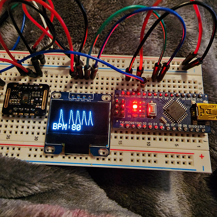
Task 3. Show BPM,
SPO2 and Waveform plot on the OLED (week 2, 30 points)
Task 4. Generate
a BOM (bill of materials) spreadsheet to include all the parts that you
need for the project and the cost. Plan for a workshop for high school
students. The plan including:
1. How long is the workshop?
We would make the workshop
two days each an hour and half long.
2. What are the final products students are going to build?
Initially the students
will start off with a simple LED project such as lighting and
controlling an LED(s) through programming the Arduino.
Once the students feel
comfortable with the Arduino software and wiring hardware, we would
move onto the main project, the heart rate monitor.
This will include students
wiring all components into the breadboard and to the Arduino, then the
student can follow along writing the code.
All students will be able
to take home their kits once the workshop is over.
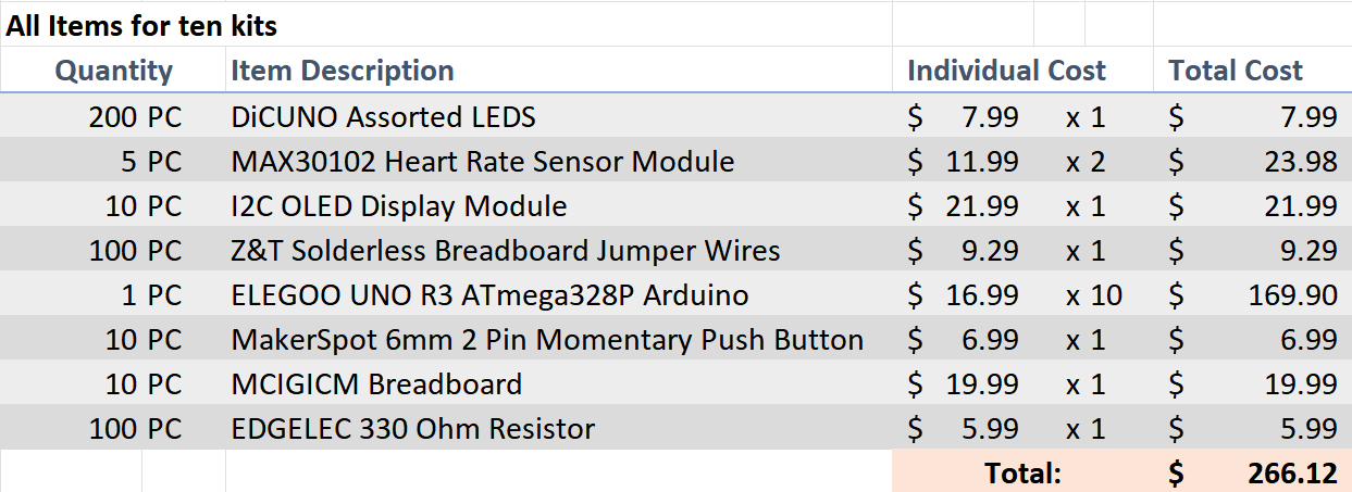
3. What are the cost of materials for each student?
All the items will be
bought in bulk to create sets of ten kits each.
Here is the itemized list
of each component:
Table 1: Itemized bill of materials
to create ten kits.
4. How much would you charge for each student?
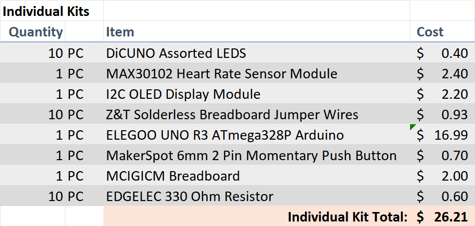
Considering that each kit
would cost us about $26.21, we can charge the students $50 to cover the
cost of the kit and workshop which would
return $23.79 in profit
per student.
Table 2: Itemized bill of materials
for a single kit.
5. How much profit you can earn from this workshop if you have 20
students registered.
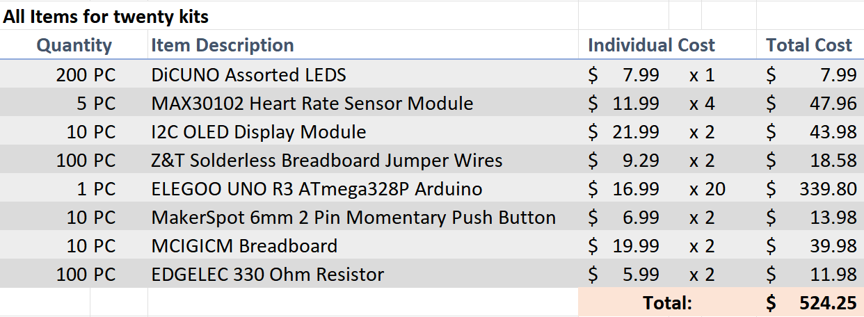
To create 20 kits, it
would cost us $524.25.
Table 3: Itemized bill of materials
for twenty kits.
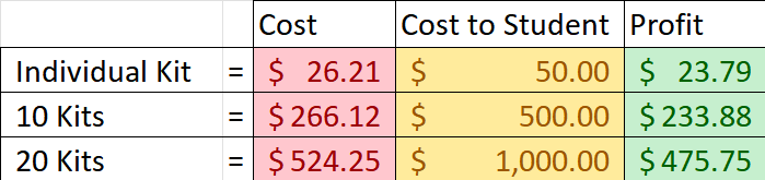
Charging each student $50
for the kit would result in a profit of $475.75 if we had 20 students
sign up.
Table 4: Cost vs profit for x
number of kits.
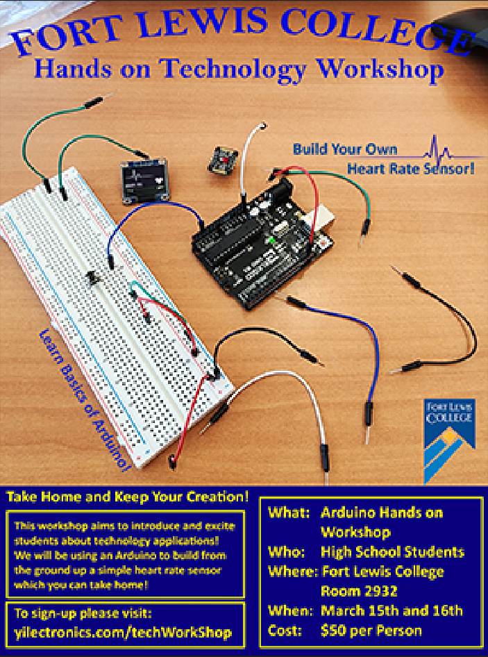
6. Design a flyer for this event to attract participants. The drawings
and art on the flyer must be original work.
Figure 13: Mock up poster/flyer for
the workshop.
7. Design a webpage to include a Dummy Paypal option on it for
customers to checkout.A
tutorial on Paypal App.Use
you CE351 page to do this.
You can also use GPay or other Apps as long as it
works.
Here is a dummy paypal payment
button.
8. Finish your first drawing
I have little to no 3D design for 3D printing. So, I
came up with a simple box to house the standalone oximeter and battery.
Video 1:
I've designed a simple box to house the oximeter and the 9V battery
powering the device. The top compartment is for the oximeter PCB board
and the bottom is for the 9V battery.
9. New PCB submitted
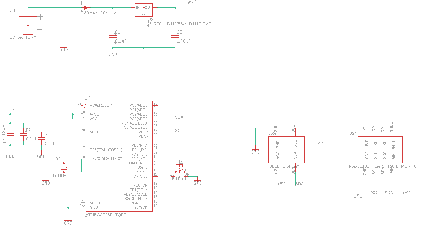
A schematic was created for a stand alone device.
Here's the schematic: Figure 14: PCB schematic.
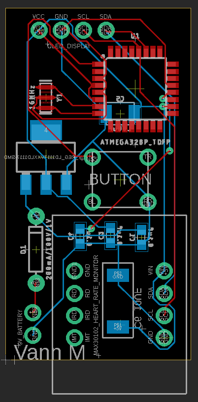
Here's the pcb design: Figure 15: PCB board design.
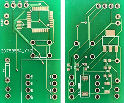
Here's the finished PCB, both front and back: Figure 16: Fabricated PCB boards.
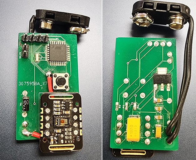
Now to solder all the components to the board: Figure 17: PCB board soldered.
Now, unfortunately, I realized that there were a few errors with my
original schematic and PCB design (have since updated and fixed the
issues) where I accidentally shorted the battery together.
Also, I noticed that one of my ground traces was not connected and had my button wired incorrectly.
I tried to remedy the situation by tearing up the trace that shorted
the battery and added a few new connections to complete the ground
connections.
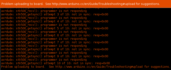
However, I could not get the board to communicate with the Arduino IDE
and due to the previous errors, I'm not sure what the cause is.
When trying to program the ATMEGA chip, I am met with the following error: Figure 18: Arduino IDE error.