CE 351 2023 Spring
Four-Wheel Smart Robot Car
Name: Vann Montoya Email:
bvmontoya@fortlewis.edu
Four-Wheel Smart Robot Car
Introduction
The purpose of this assignment is to bring together
multiple components, devices and sensors to create a smart robot car.
Materials and Methods
Arduino
Ultrasonic sensor
Infrared sensor
Servo
Line Tracking
4 DC Motors
Tires
Results Task
1:To
assemble the car, please follow the tutorials in the following video
series. Please take GOOD care of the small parts of the car when you
assemble it.
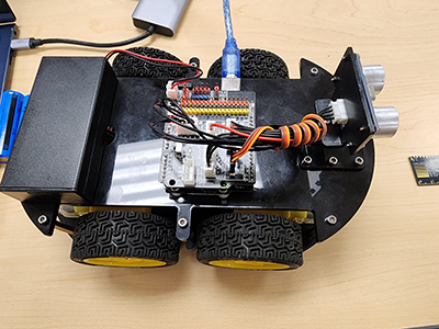
Here is the car fully assembled: Figure 1:
Fully assembled car.
Task
2:Just repeat what I did in the video above. Take screenshotes or
videos for your report. You will use the same ultrasonic sensor in the
robot car kit.
Here's the video demonstrating the ultrasonic sensor
working:
Video 1:
Demonstrating ultrasonic sensor.
Task
3:Understant the code and repeat it on your side.
Take VIDEOs for your report.
This next task is to demonstrate the servo motor on
the car which controls the direction of the ultrasonic sensor.
Here's a video demonstrating the servo moving: Video 2:
Servo motor demonstration.
Task
4:Use the example code to turn on the
motors of the car, take VIDEOs for the report.
Next task is to make the car move using the DC
motors aboard the car.
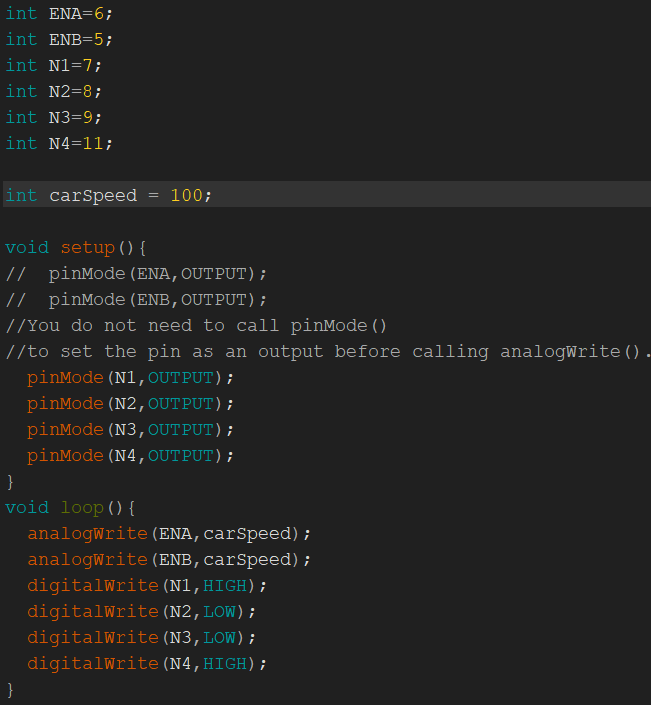
In this case, I set the PWM to 100, which is just
under half the total power (255) to make sure the car doesn't
immediately take off. Figure 2: Car
movement code set with a PWM of 100.
Here's the video demonstrating the car moving on its
own: Video 3: Car
movement demonstration.
Task
5:Repeat my work in the demonstration video and
use the similar method to test the Right and the Left IR
emitter-receiver pairs.
For this task, I went ahead and updated the code to
display when the line is on the left, middle, or right IR
emitter-receiver sensor.
Here's a video demonstrating the IR emitter-receiver
pairs:
Video 4: IR emitter-receiver pairs.
Task
6:Complete
the code for Mode 1: Only after pressing '1' to enter Mode 1, then go
places!
Task
7:For
Mode 2, complete the code for the car for the 'Go Places' and the 'Line
Tracker' mode. You must use the remote controller to switch the modes.
Task
8:Embed
this Obstacle Avoidance strategy into your entire code. The final
demonstration must be done in ONE Sketch (one sketch covers all the
three modes).