CE351 2023 Spring ESP32
WiFi-BT-BLE MCU Module / ESP-WROOM-32 Name: Vann Montoya Email:
bvmontoya@fortlewis.edu
ESP32
WiFi-BT-BLE MCU Module / ESP-WROOM-32 Introduction
The purpose of this assignment is to become familiar with theESP32
WiFi-BT-BLE MCU Module using the Arduino IDE.
Materials and Methods ESP32
WiFi-BT-BLE MCU Module
Arduino IDE Results Task
1: Use
the Arduino IDE to program the ESP32 Module with a simple blink program.(10
points)
Video
1: Demonstrating
the ESP32 module programmed with a simple blink program. Task
2:Communicating
with the MPU6050 Accelerometer and Gyroscope using the ESP32 Module.
(10 points)
Video 2: Demonstrating the ESP32 communicating with
accelerometer and displaying the results to the serial plotter.
Task
3:Convert
the X, Y, Z readings into g's and display a smooth plot. (10
points)
Video 3: Demonstrating the ESP32 communicating with the accelerometer and displaying to the serial plotter in G's.
Task
4:Communicate and write to the SD card using the ESP32(10
points)
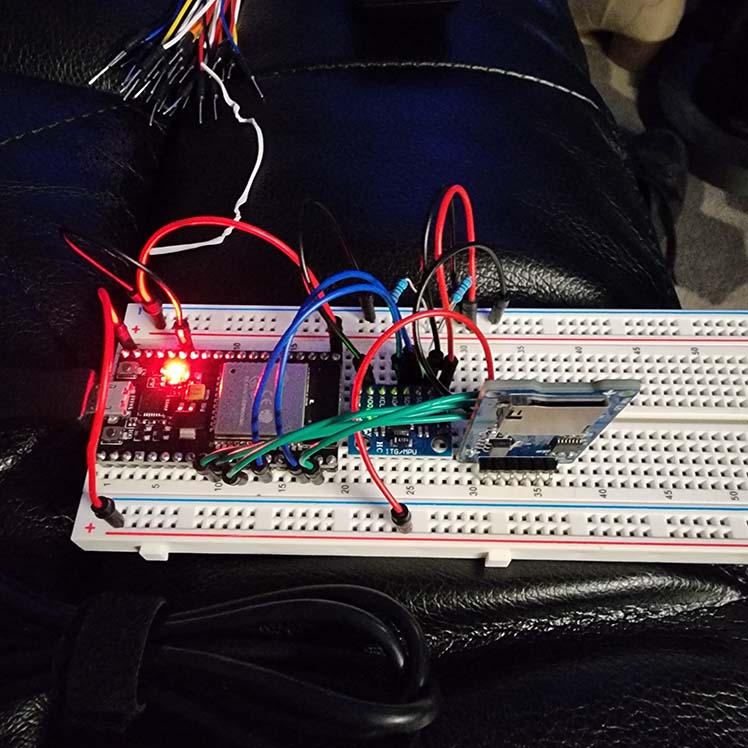
Figure 1: The ESP32 Module wired with the SD card module.
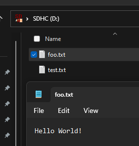
Figure 2: Test files being read from the SD card that were created using the ESP32 and SD card modules.
Task
5:Read X, Y, Z data from the accelerometer and write to the SD card, then use Python to plot the data. (10
points)
Figure 3: The ESP32 module connected with the accelerometer and SD card module.
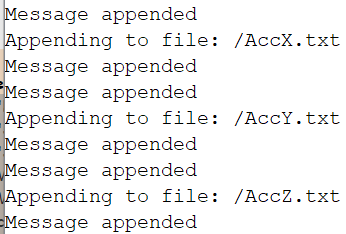
Figure 4: The serial monitor reporting that the X, Y, and Z, readings have been successfully written to their text files on the SD card.
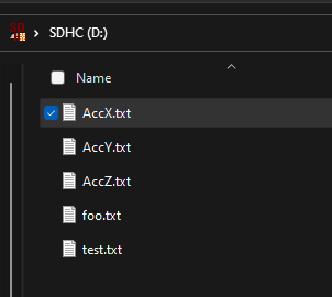
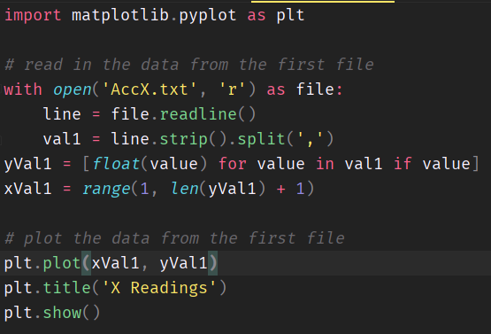
Figure 5: Reading from the SD card shows X, Y, and Z text files written successfully to the SD card. Now we wantto create a python script to plot the data from the .txt files.
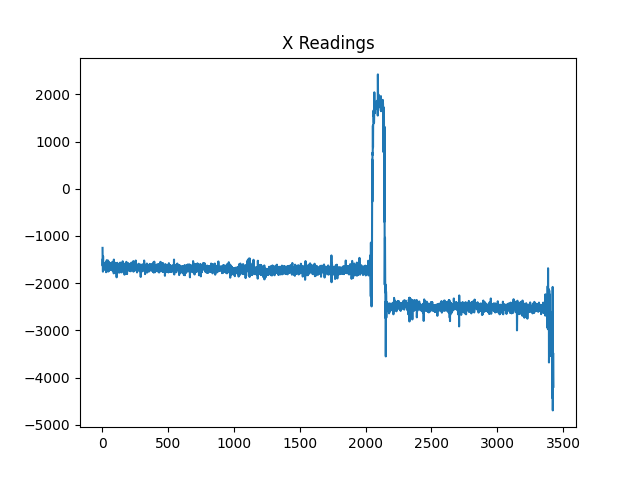
Figure 6: Python script file for reading from the data and plotting Figure 7: Python generated plot from the data.
Task
6:Convert the data to G's, read from the SD card and plot using Python(10
points)
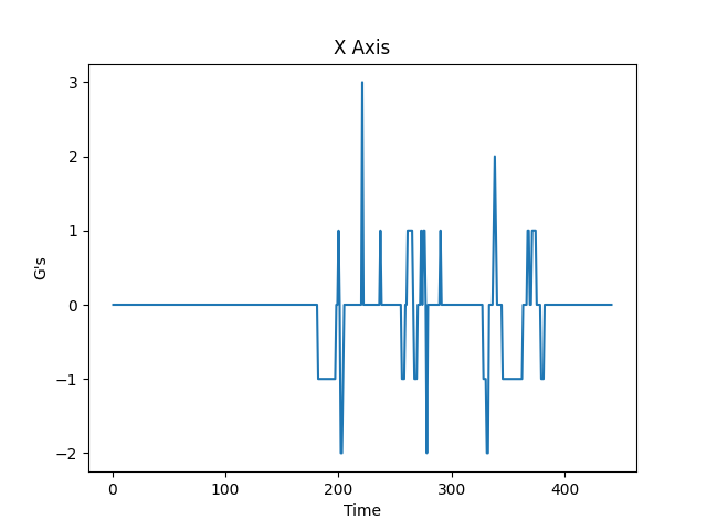
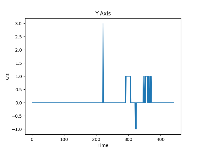
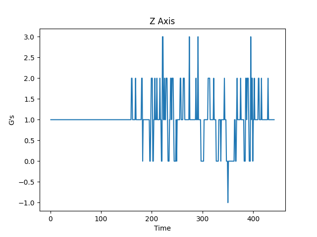
Figure 8: Plots created using Python reading from the accelerometer data.
Task
7:Using two ESP32 modules, communicate between both using the WIFI module and display the data. (10
points)
For
this section of the assignment, I tried so many different times to get
the two ESP32-S Modules to communicate with one another.
I used the code provided for both the master and slave, made sure to
check the MAC address for the slave module, tried different ESP32
modules, swapped the two,
however, no matter what I tried I could not get it to work.
On the slave module I was not able to receive the data from the master and only displayed zeros for all received values.
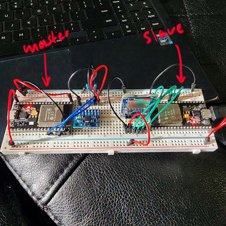
Figure9: Two ESP32-S Modules, one for reading data and sending, the other for receiving and storing the data.
Task
8:Using the two ESP32 modules, read the accelerometer data and store it on the SD card.(10
points)
Task
9:Clean up the code for both master and slave modules, save the accelerometer data to the SD card and plot the results.(20
points)