CE 388 Lab 2023 Fall
Lab 8 Design a MUX, and High-Speed
Full Adder
Name: Vann Montoya
Email: bvmontoya@fortlewis.edu
Design
a MUX, and High-Speed Full Adder
Introduction
Materials and Methods
Results
Task 1: Build an 8-bit MUX. (20 points)
First, we want to build the single bit MUX starting with the schematic.
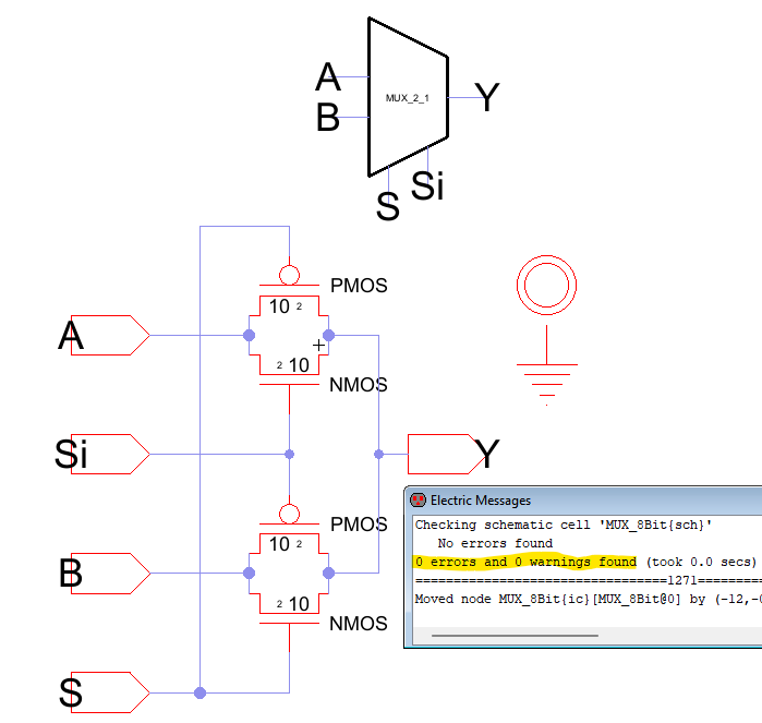
Figure 1: Single Bit MUX Schematic and Icon with no Errors.
Now to make sure it works by running a simulation.
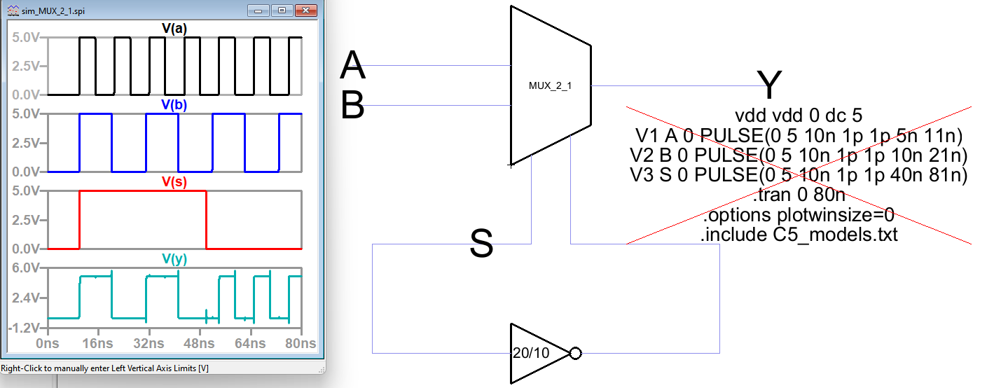
Figure 2: Single Bit MUX Simuation and Result.
Now, to create the layout for the single bit MUX.
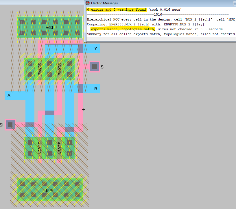
Figure 3: Single Bit MUX Layout with no Errors.
Now, to begin on the 8-Bit MUX starting with schematic and icon.
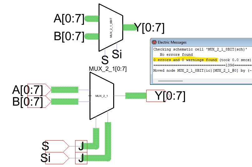
Figure 4: 8-Bit MUX Schematic and Icon with no Errors.
Run the simulation for the 8-Bit MUX.

Figure 5: 8-Bit MUX Simulation and Results.
Lastly, the layout for the 8-Bit MUX.
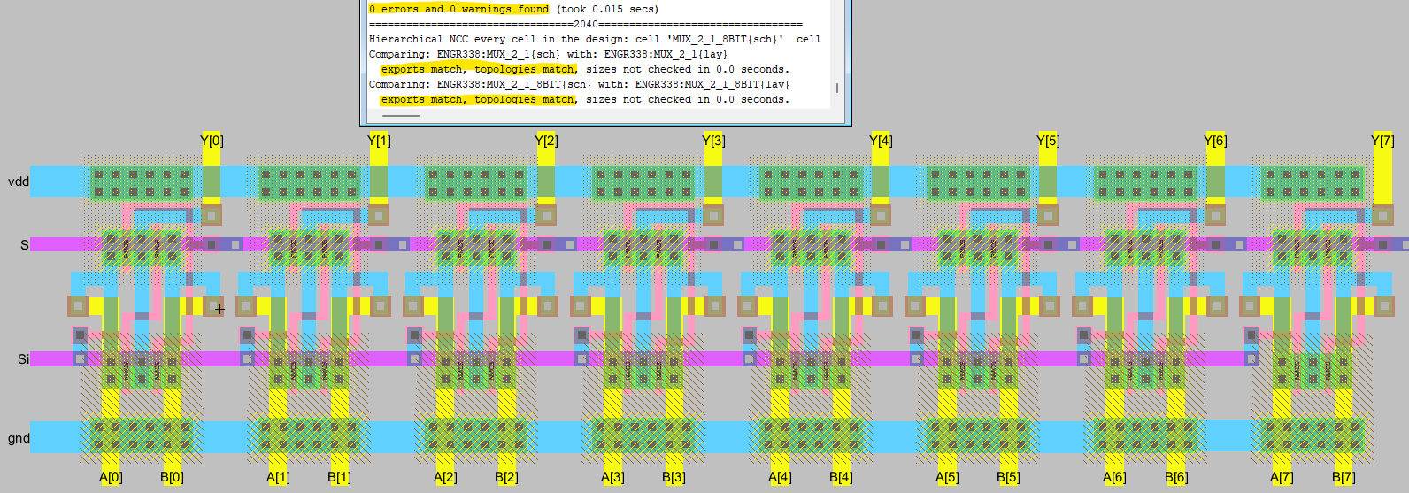
Figure 6: 8-Bit MUX Layout with no Errors.
Task 2: Build a 1-bit high-speed full adder. (40 points)
Next is to create the single bit high speed full adder and run a simulation to ensure it is working correctly.
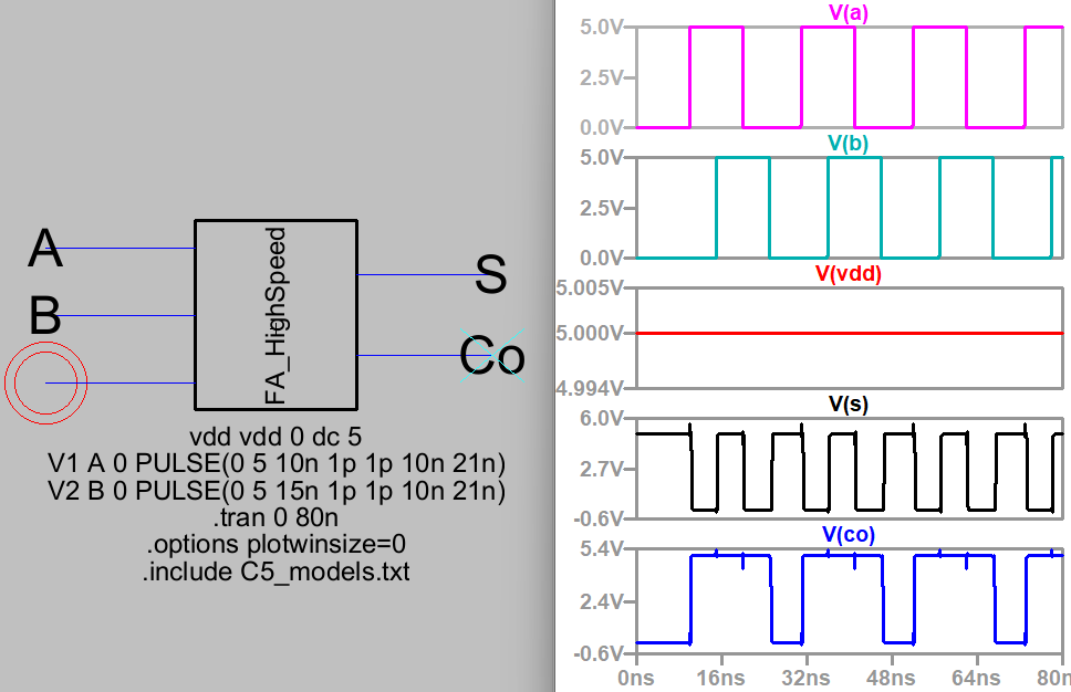
Figure 7: Single Bit High Speed Full Adder Simuation and Result.
Now, to tackle the layout.
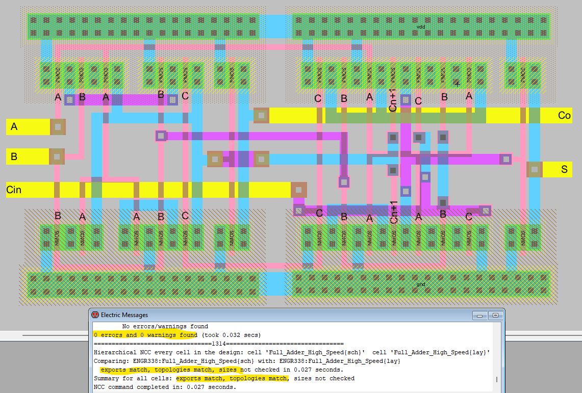
Figure 8: Single Bit High Speed Full Adder Layout with no Errors.
Task 3: Build an 8-bit high-speed full adder. (30 points)
Now, to begin on the 8-Bit High Speed Full Adder starting with schematic and icon.
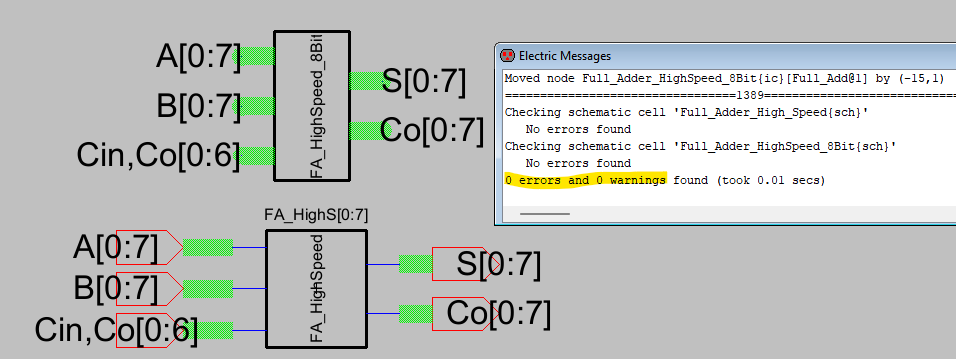
Figure 9: 8-Bit High Speed Full Adder Schematic and Icon with no Errors.
Next, we want to run a couple of simulations to verify the logic of the Full Adder.
For the first simulation, we are setting A = 11111110 and B = 10000000
which should result in S = 01111110 and a Carry of Co[7] = 1.
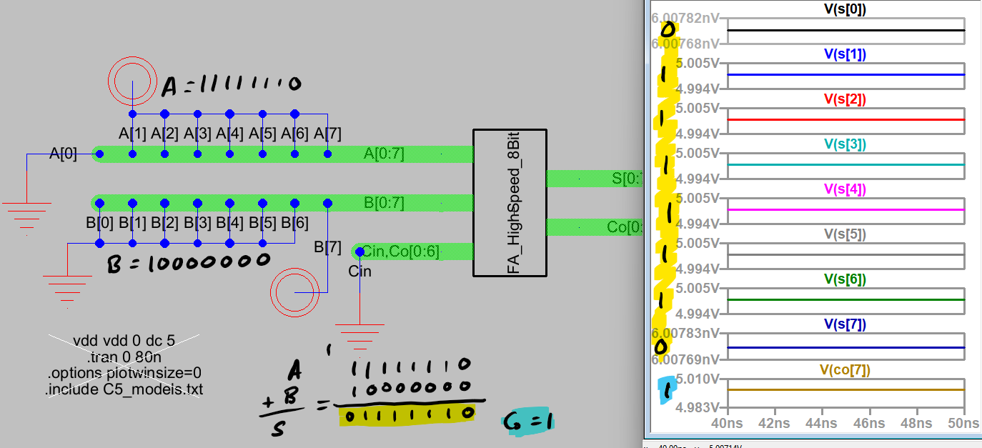
Figure 10: 8-Bit High Speed Full Adder Simulation and Results.
Next simulation, we are setting A = 01101010 and B = 10001010 which should result in S = 11110100 and Co[7] = 0.
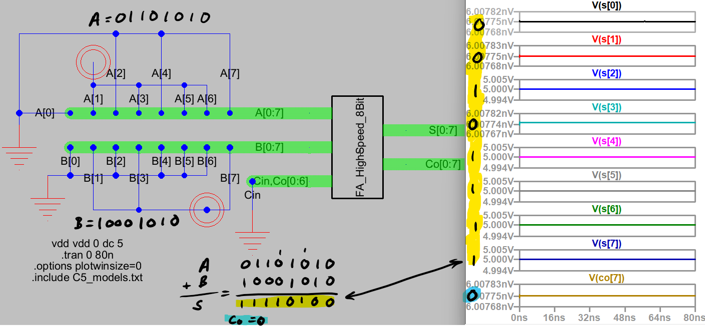
Figure 11: 8-Bit High Speed Full Adder Simulation and Results.
Last simulation, we are setting A = 11010110 and B = 10100101 which should result in S = 01111011 and Co[7] = 1.
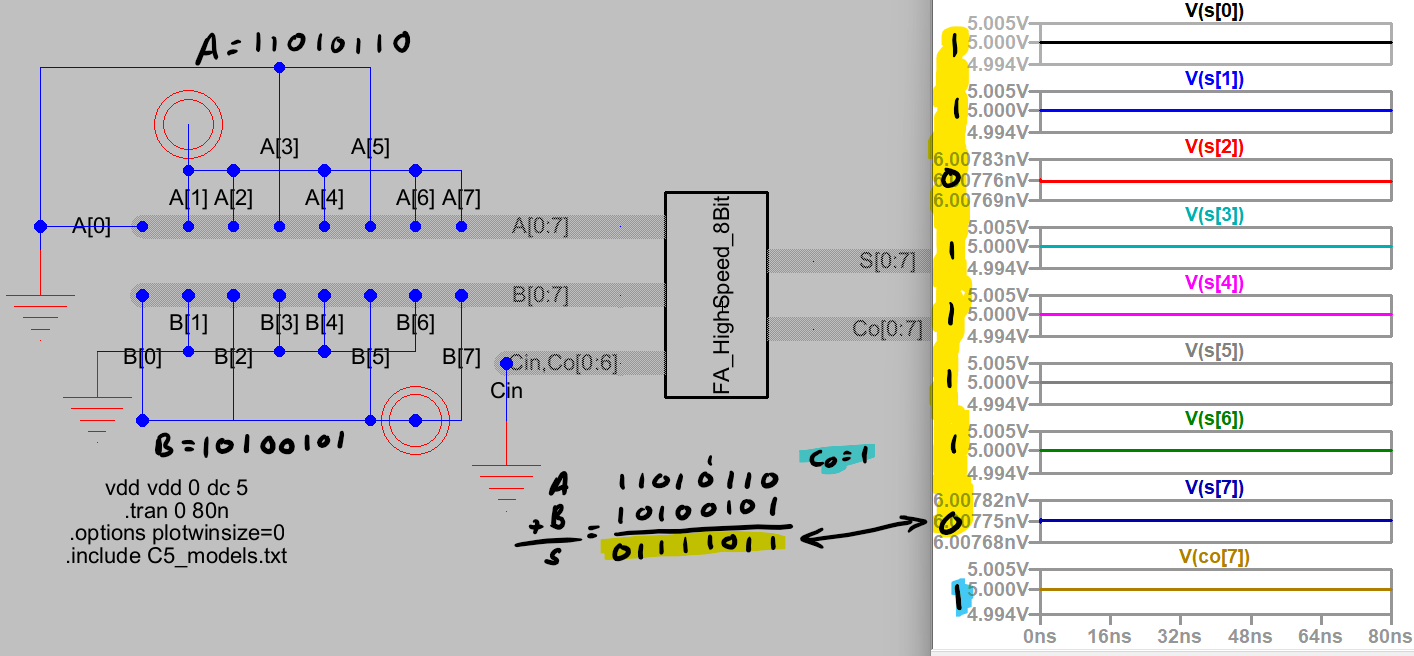
Figure 12: 8-Bit High Speed Full Adder Simulation and Results.
Lastly, to tackle the layout for the 8-Bit High Speed Full Adder.
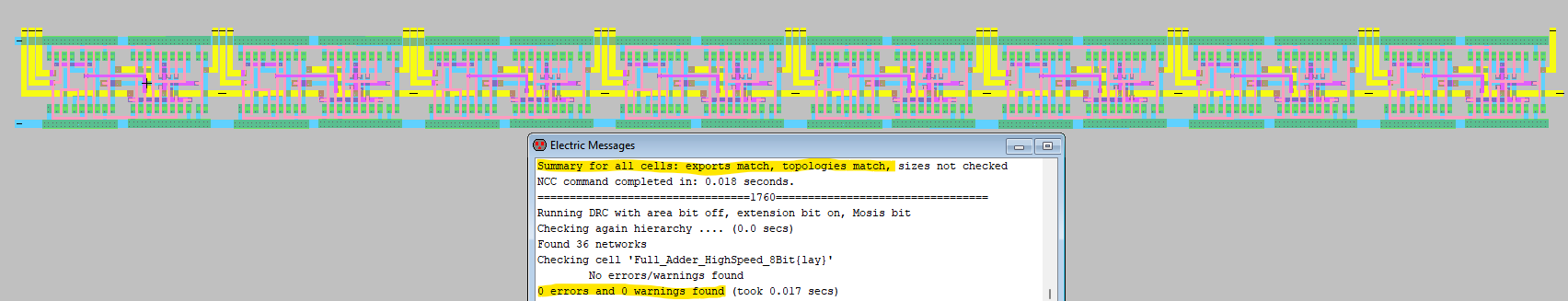
Figure 13: 8-Bit High Speed Full Adder Layout with no Errors.
Discussion
This lab was a great way to continue practice using ElectricVLSI and getting comfortable with layout.