ENGR 338 Lab 2021 Fall
Lab 8
Name: Brian Tsosie
Email: bjtsosie@fortlewis.edu
Using Buses in Electric VLSI
Introduction
Building an 8-bit MUX and an 8-bit High Speed Full Adder.
Materials and Methods
Pencil & Paper
|
LT Spice software
|
Electric VLSI software
|
Results
Task 1: 8-bit MUX
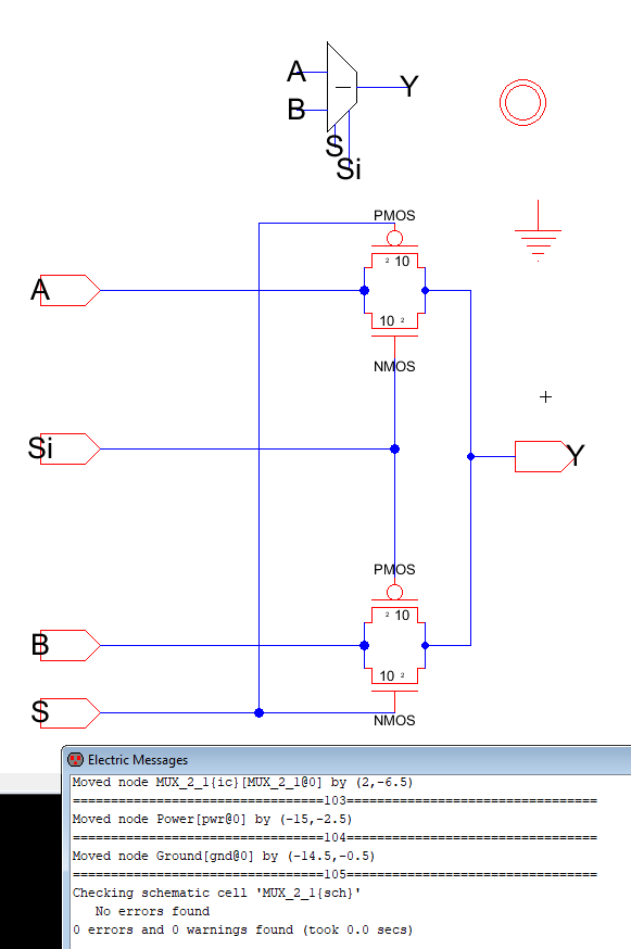
Figure 1. Basic 2 to 1 MUX schematic with DRC.
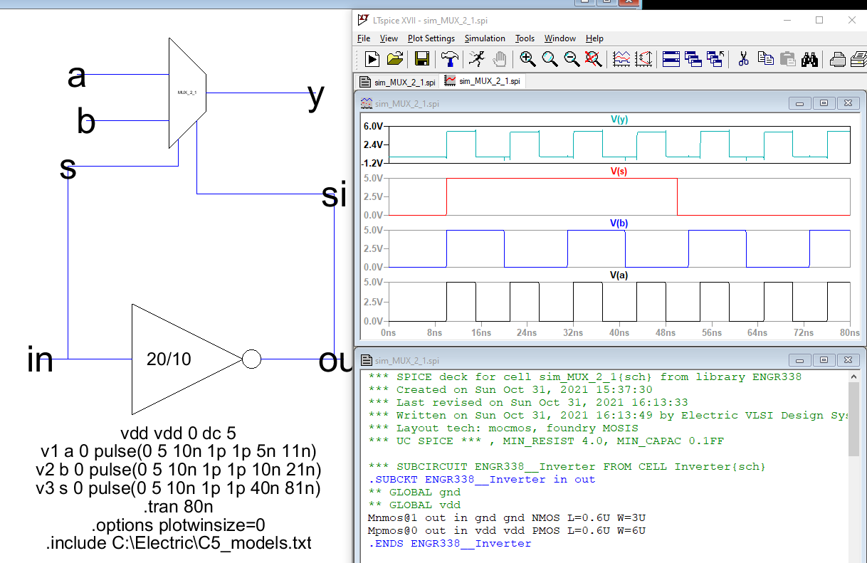
Figure 2. LTSpice MUX simulation.
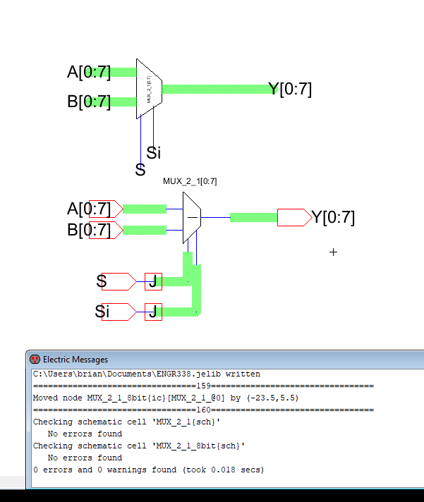
Figure 3. 8-bit MUX schematic using buses and DRC.
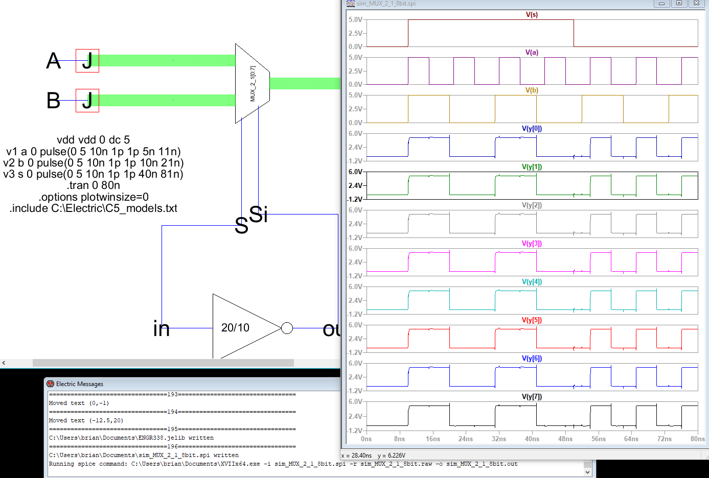
Figure 4. 8-bit MUX simulation.
Task 2: 1-bit High Speed Full Adder
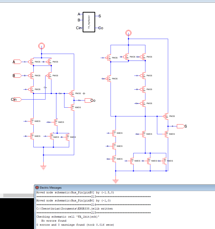
Figure 5. Full Adder schematic with DRC.
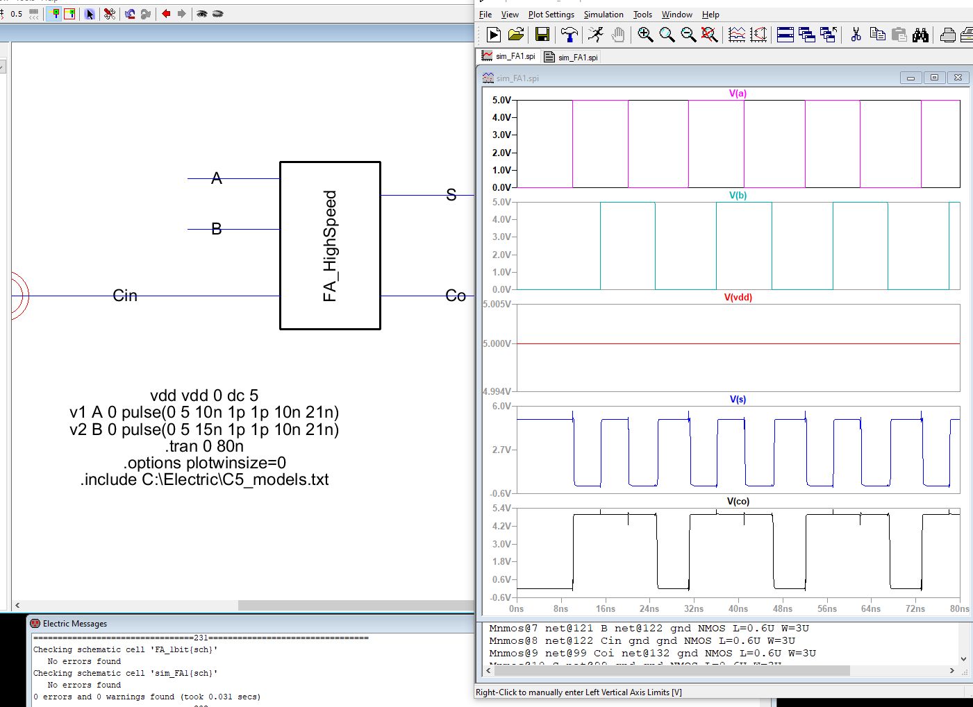
Figure 6. Full Adder simulation.
Task 3: 8-bit High Speed Full Adder
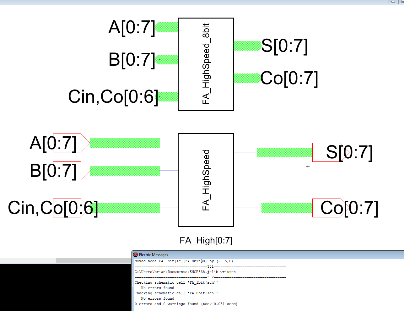
Figure 7. 8-bit Full Adder schematic with DRC.
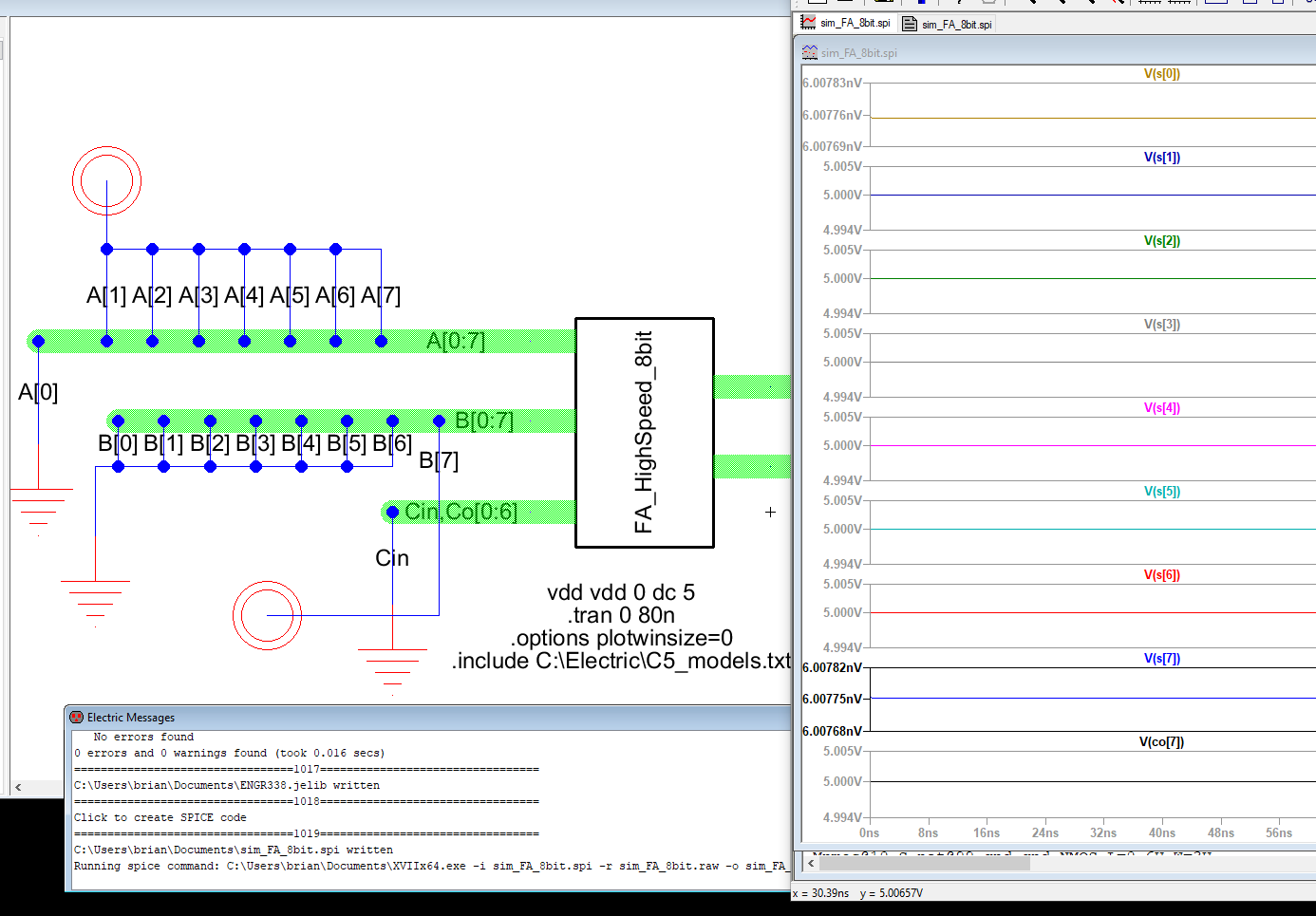
Figure 8. 8-bit Full Adder simulation.
Discussion
Building the schematic versions of a MUX and a high speed full adder
were relatively straight forward. Layout view however, can be more of a
challenge mainly because
the components have to be in just the right spot to not generate
errors. Regrettably, due to poor time management the layout view to the
following circuits were not
completed and able to be presented.