ENGR 338 Lab 2021 Fall
Lab 7
Name: Brian Tsosie
Email: bjtsosie@fortlewis.edu
Using Buses in Electric VLSI
Introduction
Using buses to build a ring oscillator, 8-bit AND, 8-bit OR, 8-bit NAND, and 8-bit NOR.
Materials and Methods
Pencil & Paper
|
LT Spice software
|
Electric VLSI software
|
Results
Task 1: Ring Oscillator
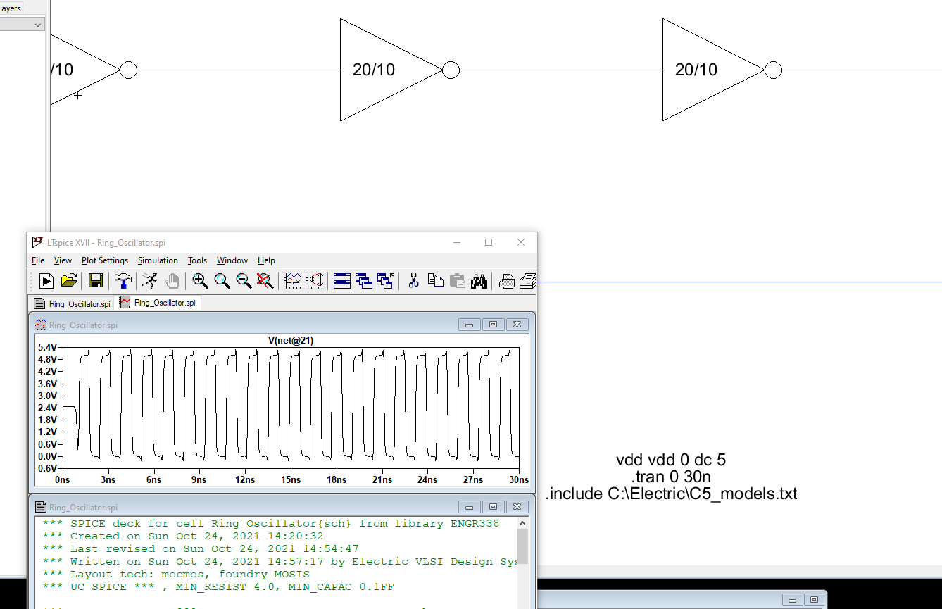
Figure 1. Ring oscillator simulation
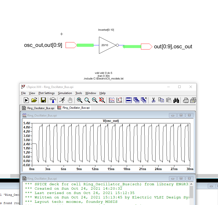
Figure 2. Ring oscillator using buses.
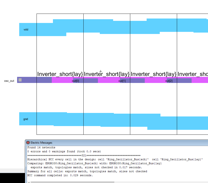
Figure 3. Layout view of the ring oscillator.
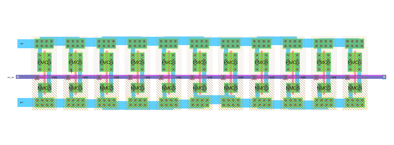
Figure 4. Internal circuit of Figure 3.
Task 2: AND gate
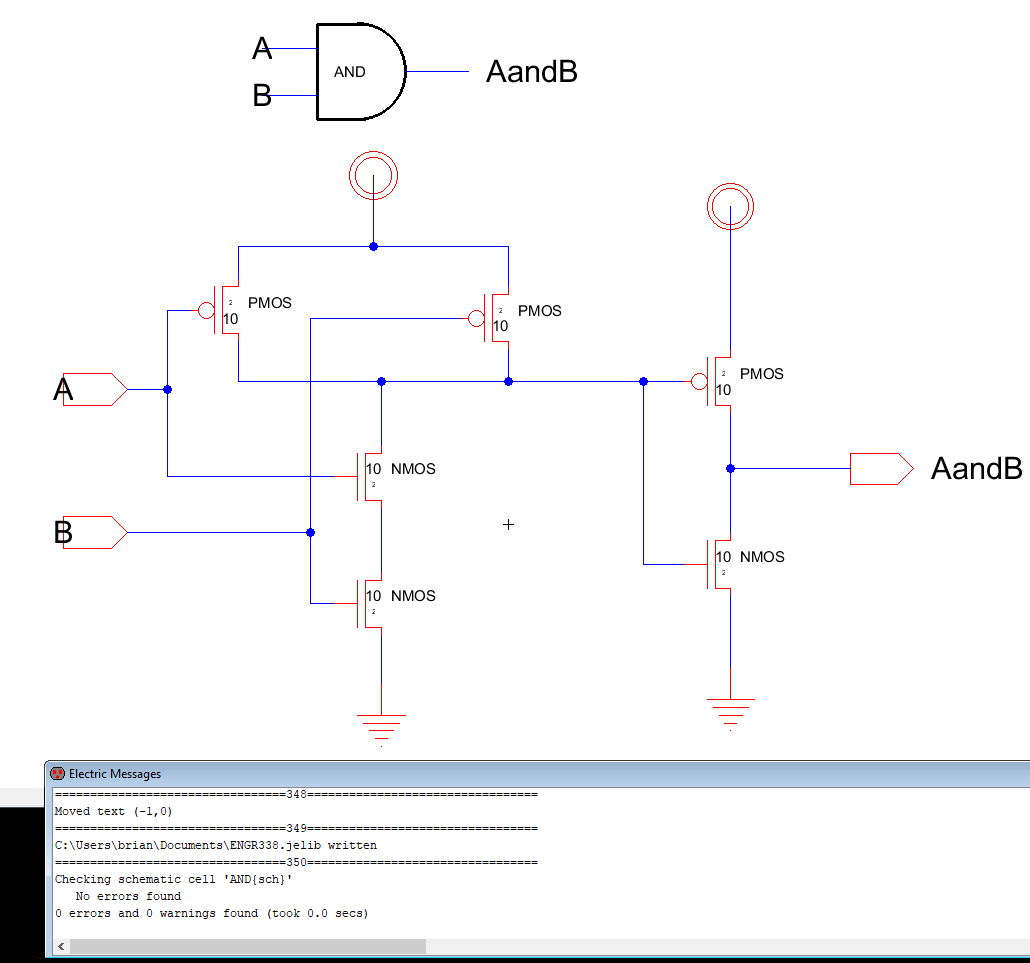
Figure 5. Schematic of AND gate with DRC.
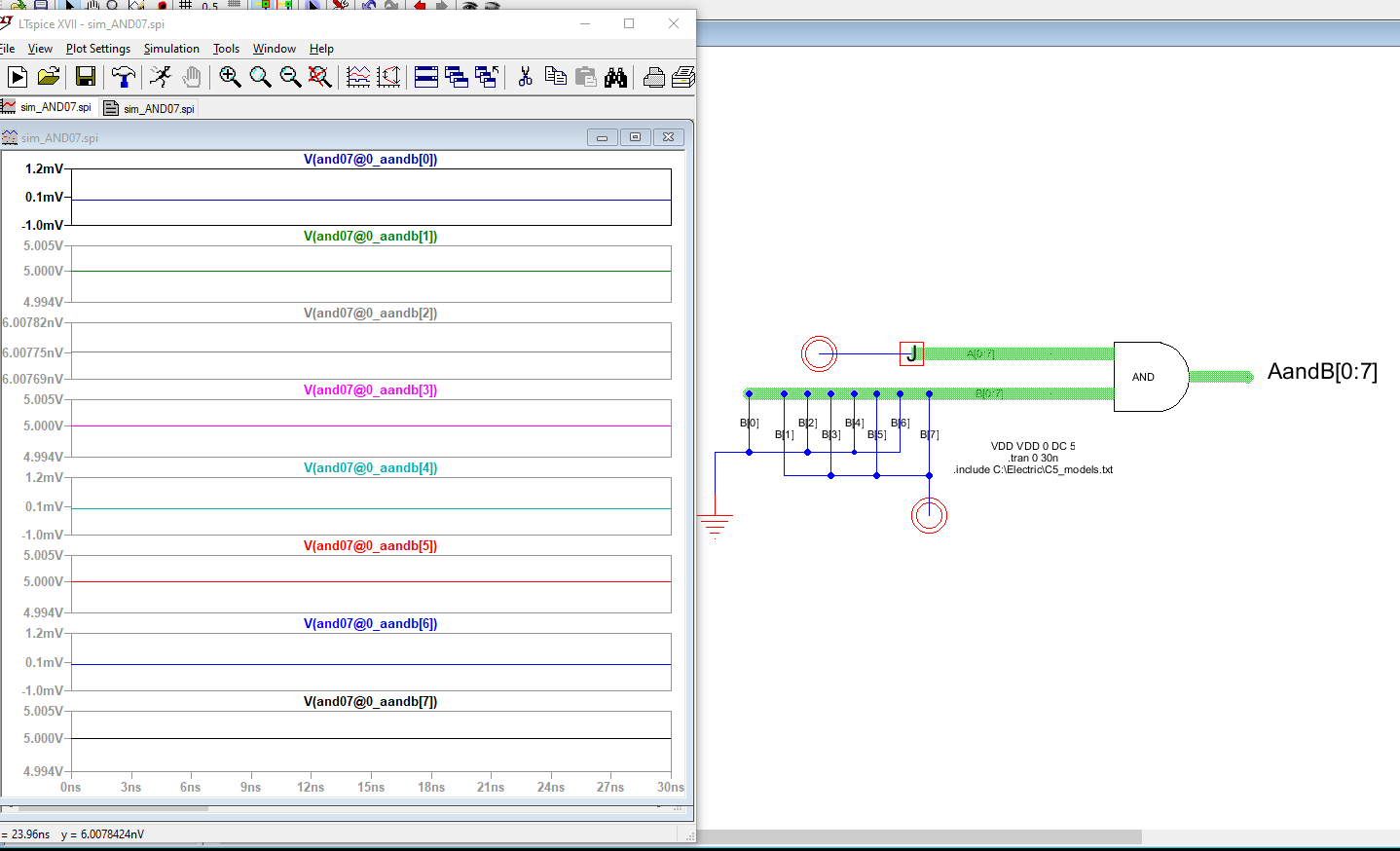
Figure 6. 8-bit AND gate simulation
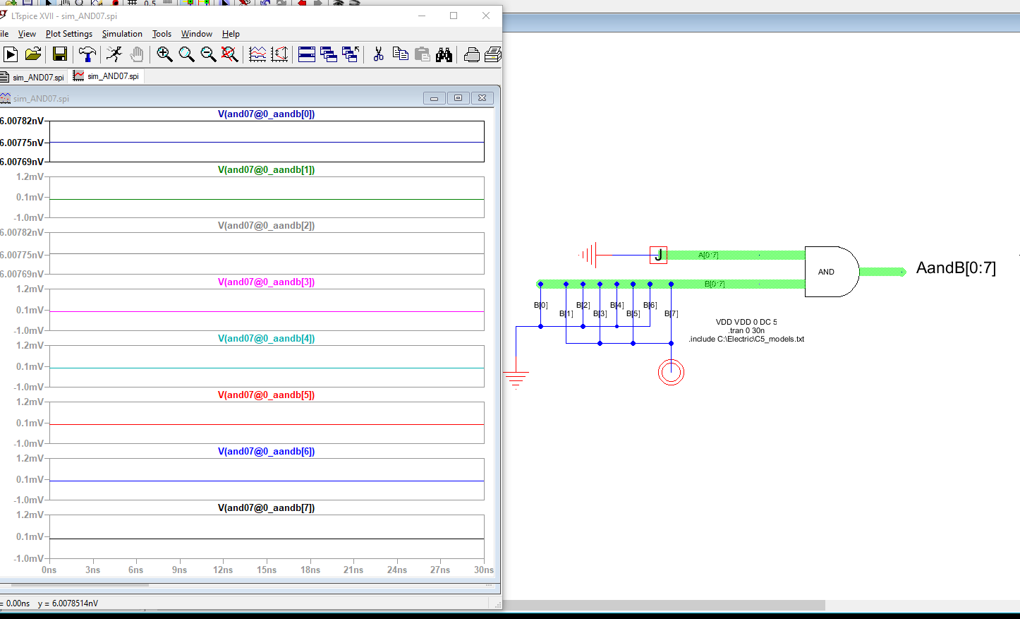
Figure 7. 8-bit AND gate simulation with bus A[0:7] grounded.
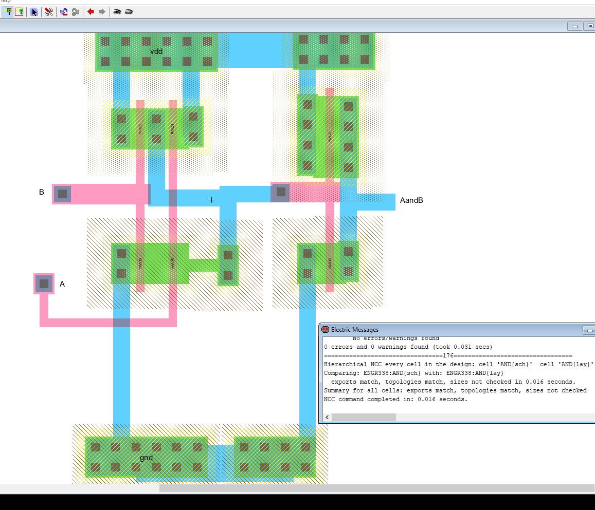
Figure 8. Layout view of AND gate with DRC and NCC.
Task 3: OR gate
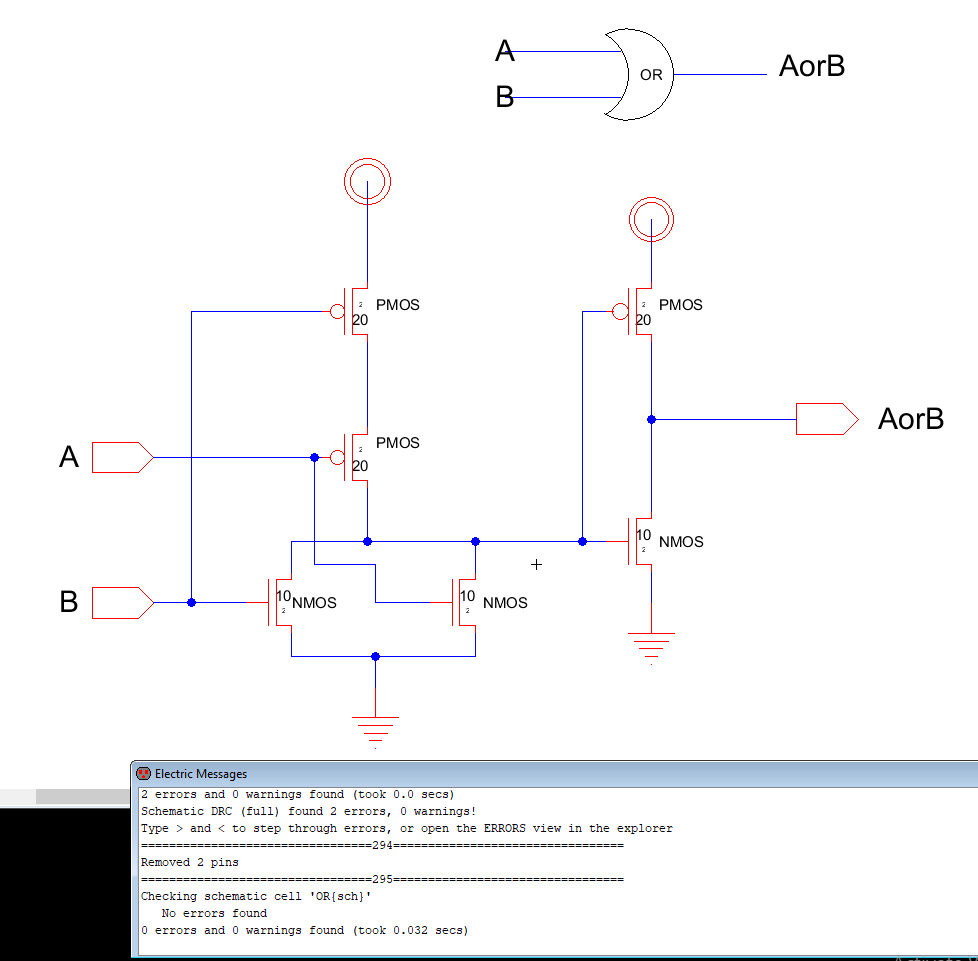
Figure 9. Shematic view of OR gate with DRC.
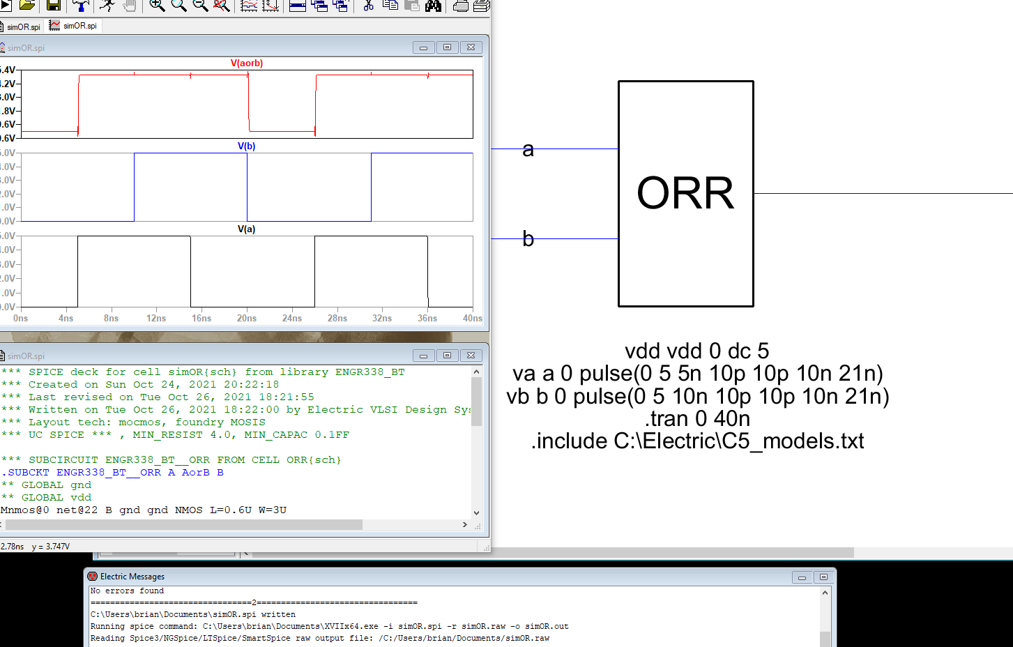
Figure 10. OR gate simulation.
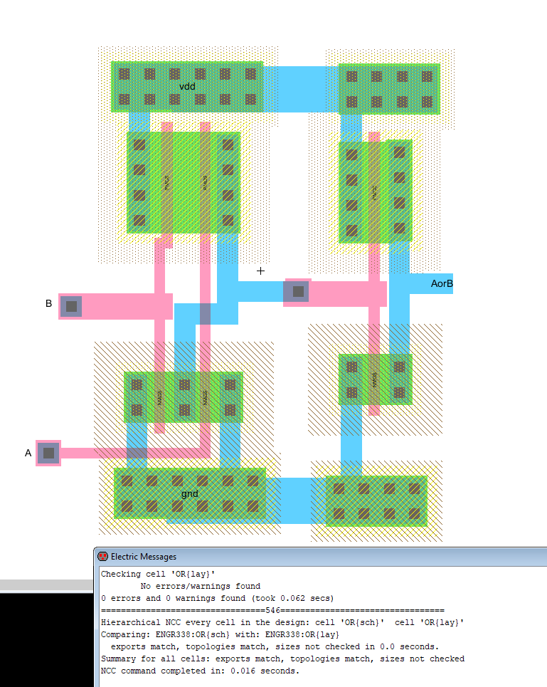
Figure 11. OR layout with DRC and NCC.
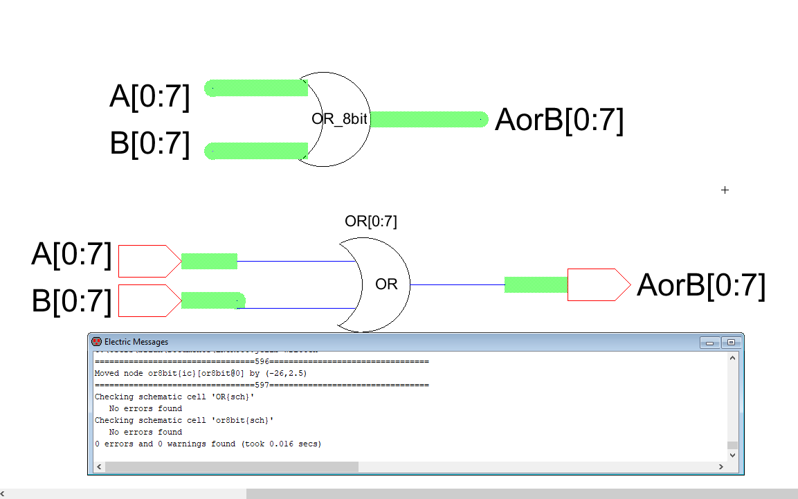
Figure 12. 8-bit OR using buses with DRC.
Task 4: 8-bit NAND gate
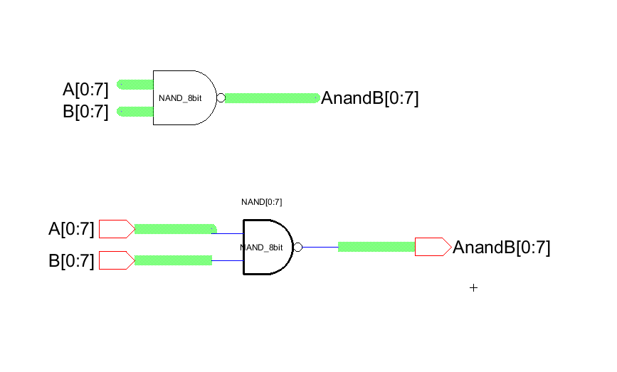
Figure 13. Schematic view of an 8-bit NAND gate using buses.
Task 5: 8-bit NOR gate
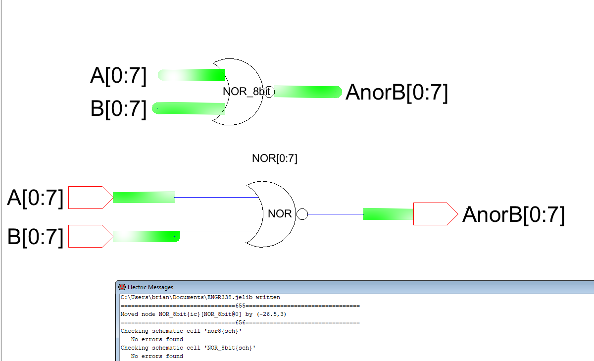
Figure 14. 8-bit NOR gate using buses with DRC.
Discussion
Gates with repetitve components or multiple inputs or outputs can
use buses to help "ease the pain" of building large circuits or gates.
Building the 8-bit
gates with buses helped build the gate faster and possibly eliminated
errors that might have occured. In layout view however, the gate or
circuit may have
to be built in its entirety without buses. This may be because building
in layout view is mimicking actual components. A bus is just a
bunch of wires
connecting two components so all the wires in a bus need to be
physically attached in layout view. This explanation is just an
educated guess based on
a personal understanding of layout view.