ENGR 338 Lab 2021 Fall
Lab 5
Name: Brian Tsosie
Email: bjtsosie@fortlewis.edu
The Inverter
Introduction
Building inverters with a single PMOS and NMOS as well as with
multiple PMOS's and NMOS's in parallel in Electric VLSI and testing in
LT Spice.
Materials and Methods
Pencil & Paper
|
LT Spice software
|
Electric VLSI software
|
Results
Task 1:
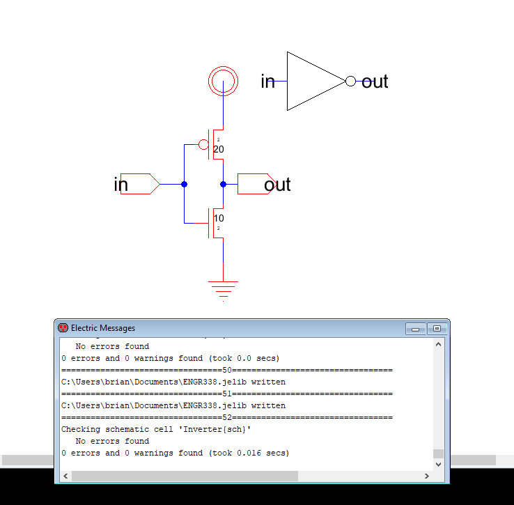
Figure 1. Schematic of the inverter and DRC.
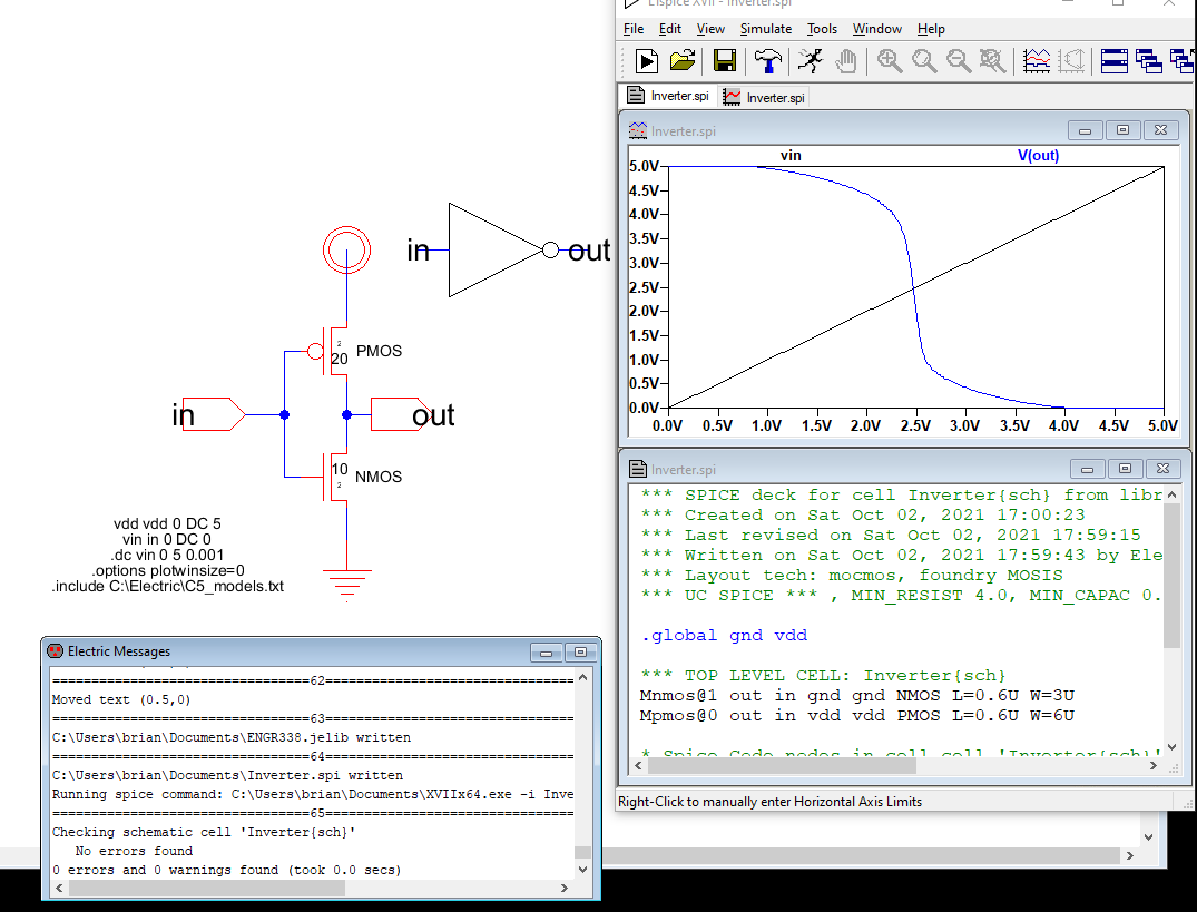
Figure 2. Inverter schematic with DRC and LT spice simulation.
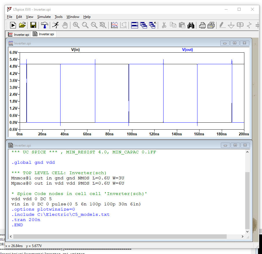
Figure 3. Transient simulation using a pulse input.
Task 2:
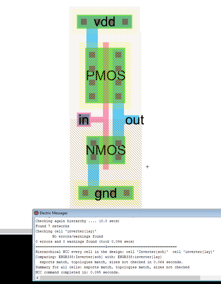
Figure 4. Layout view of the inverter and DRC.
Task 3:
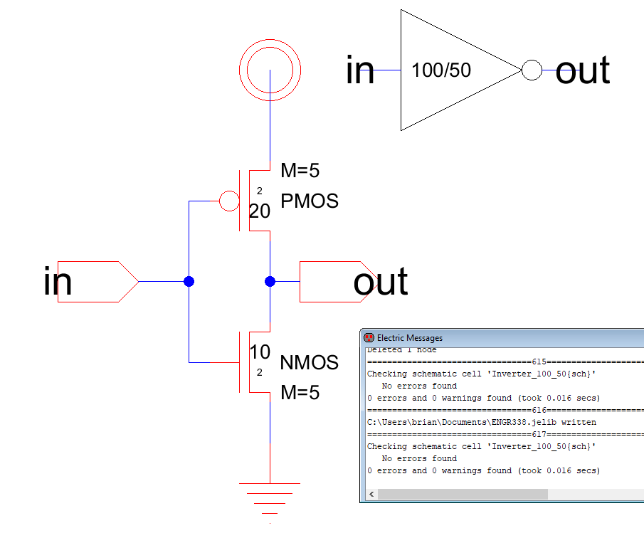
Figure 5. Schematic of inverter using the multiplier and DRC.
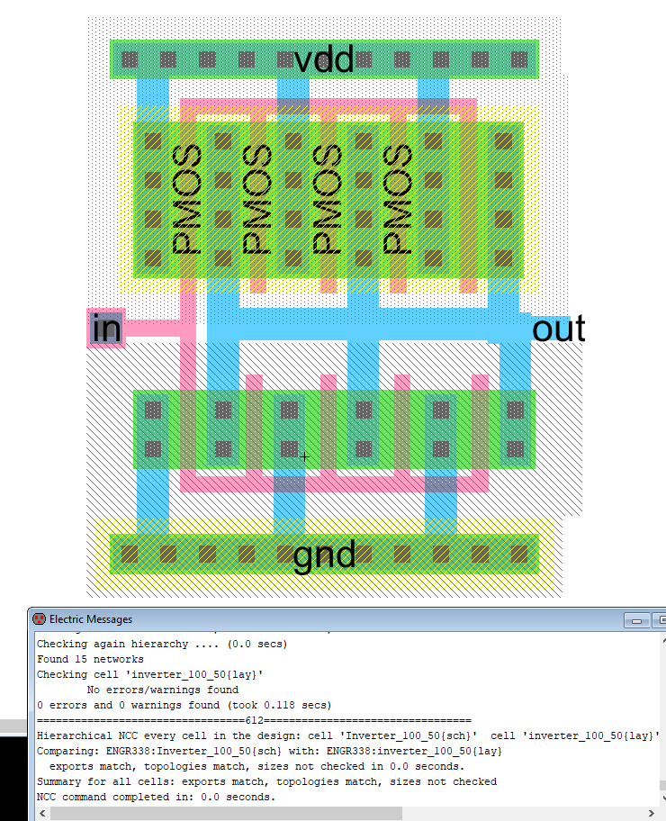
Figure 6. Layout view of 5 PMOS and NMOS in parallel with DRC and NCC.
Task 4:
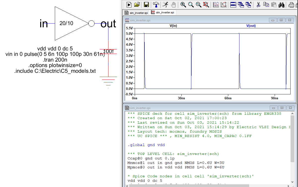
Figure 7. Simulation of the 20/10 inverter with a 100 fF capacitor.
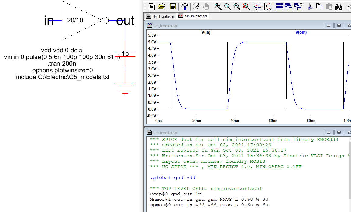
Figure 8. Simulation of the 20/10 inverter with a 1 pF capacitor.
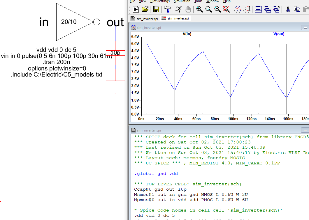
Figure 9. Simulation of the 20/10 inverter with a 10 pF capacitor.

Figure 10. Simulation of the 100/50 inverter with a 100 fF capacitor.
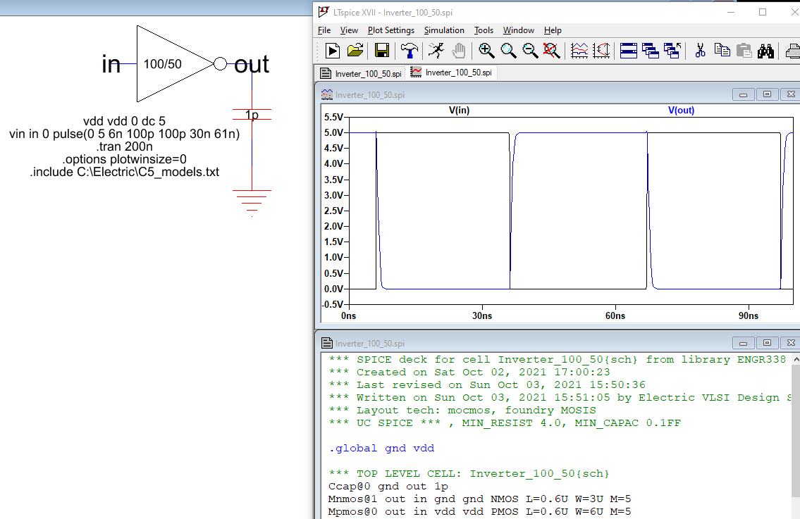
Figure 11. Simulation of the 100/50 inverter with a 1pF capacitor.
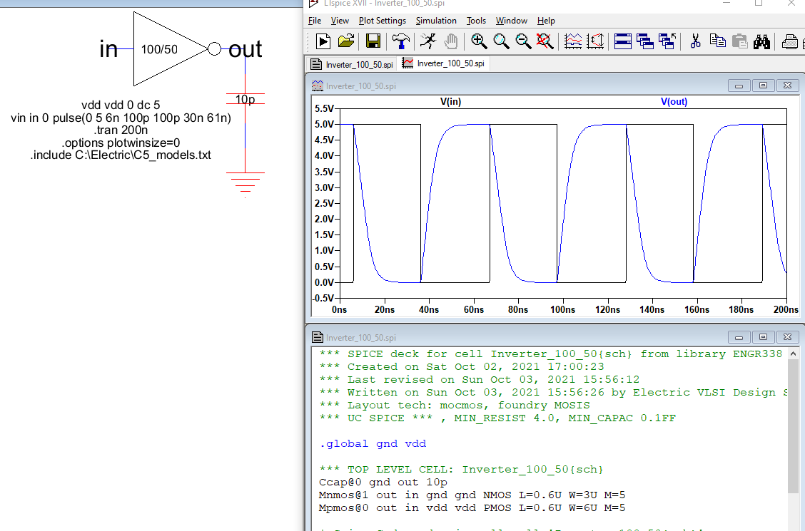
Figure 12. Simulation of the 100/50 inverter with a 10 pF capacitor.
Discussion
In this lab we built two inverters. The first inverter had
one PMOS and one NMOS transistor. It was simulated with a 5V DC
input. The
second inverter was the same as the first but we multiplied each PMOS
and NMOS transistor by five. In the schematic view, we told
Electric
to add a multiplier equal to five, M=5. In layout mode, we
actually had to build the PMOS and NMOS transistors and put them in
parallel.
It was a very time consuming task with many errors through out the
build. After a couple of hours, the DRC and NCC passed.
Toward the
end of the lab the output of the two inverters were connected to tree
different size capacitors and simulated. A 100 fF, 1 pF, and a 10
pF
capacitor were used. As the capacitance got bigger, the inverter
with only two transistors had difficulties reaching the full
voltage. The
inverter with the multiple transistors in parallel seemed to have and easier time.