Results
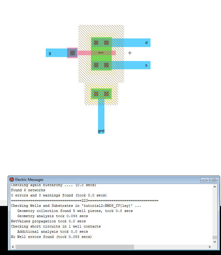
Figure 1. NMOS in layout mode.
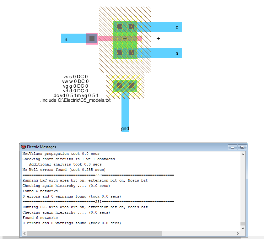
Figure 2. NMOS layout with LT Spice code.
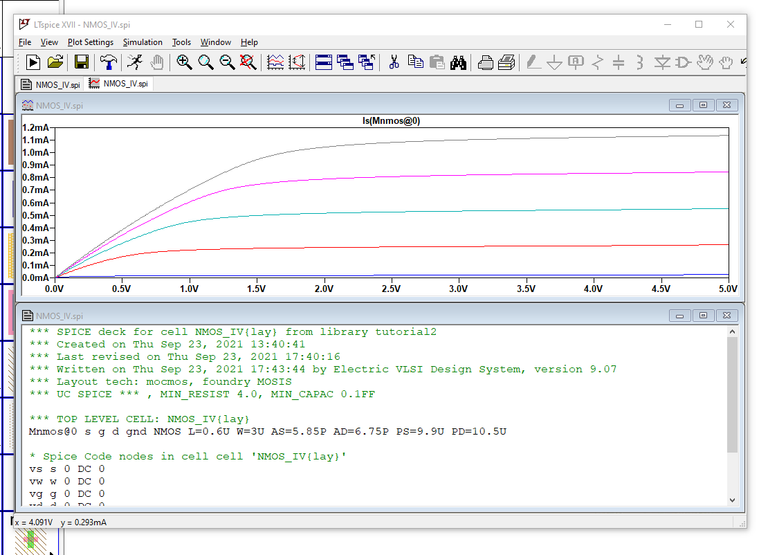
Figure 3. NMOS layout simulation.
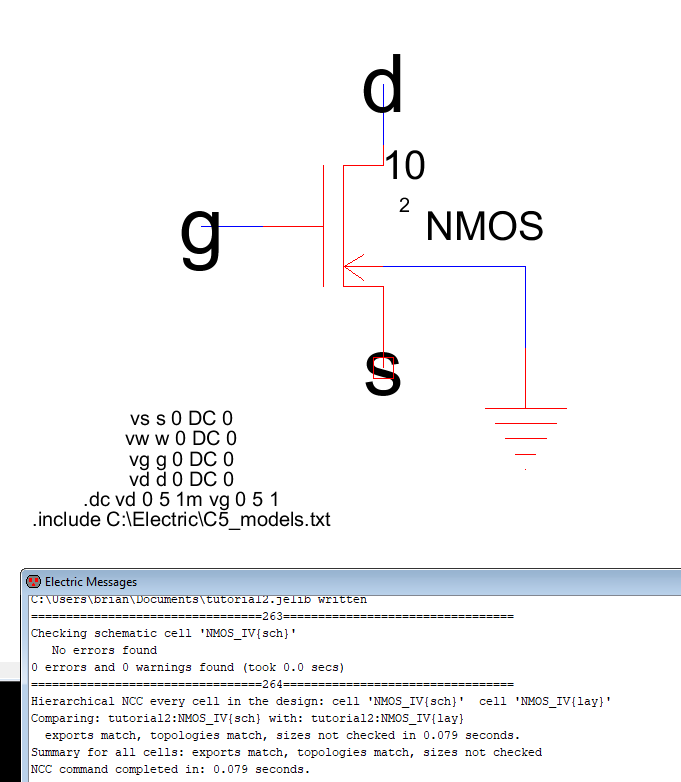
Figure 4. NMOS schematic with LT Spice code.
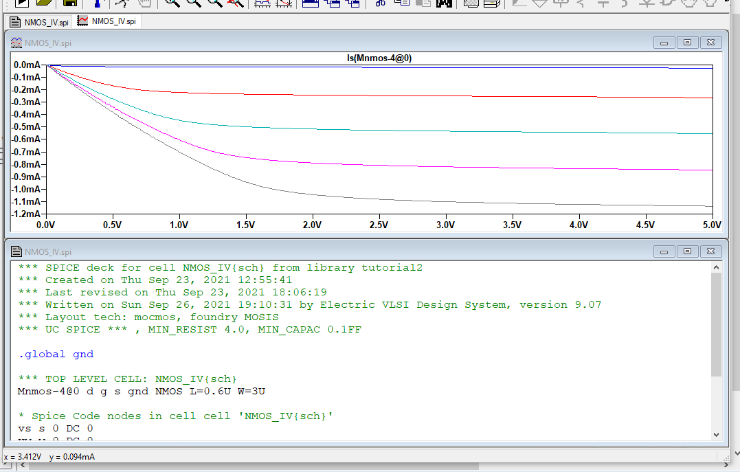
Figure 5. NMOS schematic simulation.
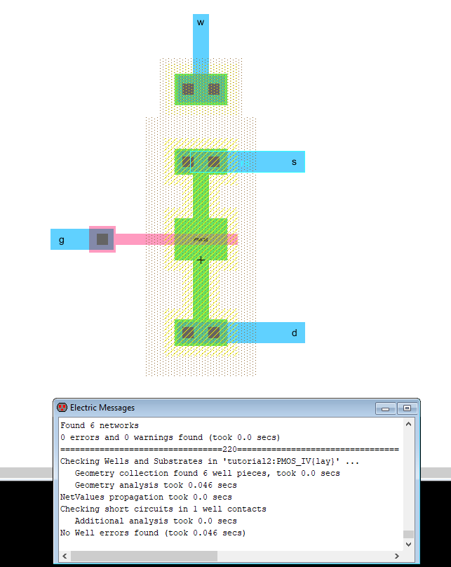
Figure 6. PMOS in layout mode.
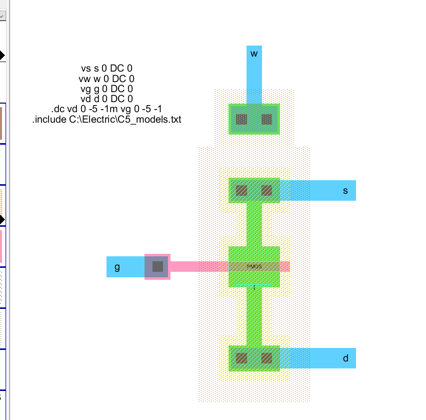
Figure 7. PMOS layout with LT Spice code.
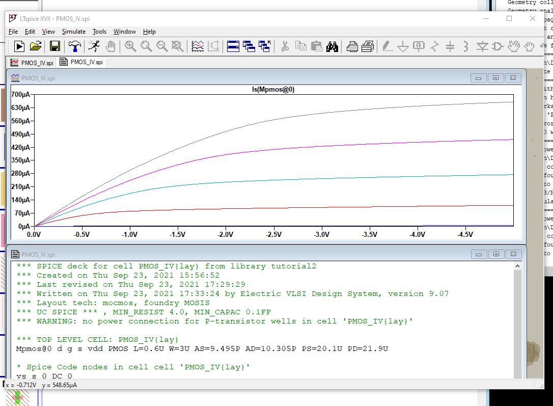
Figure 8. PMOS layout simulation.
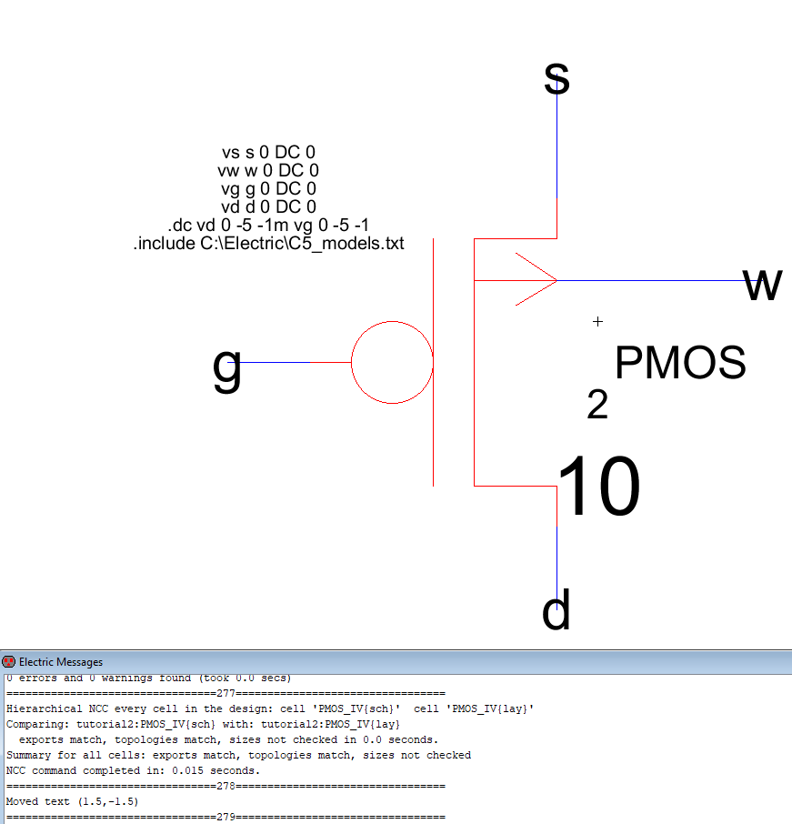
Figure 8. PMOS schematic with LT Spice code.
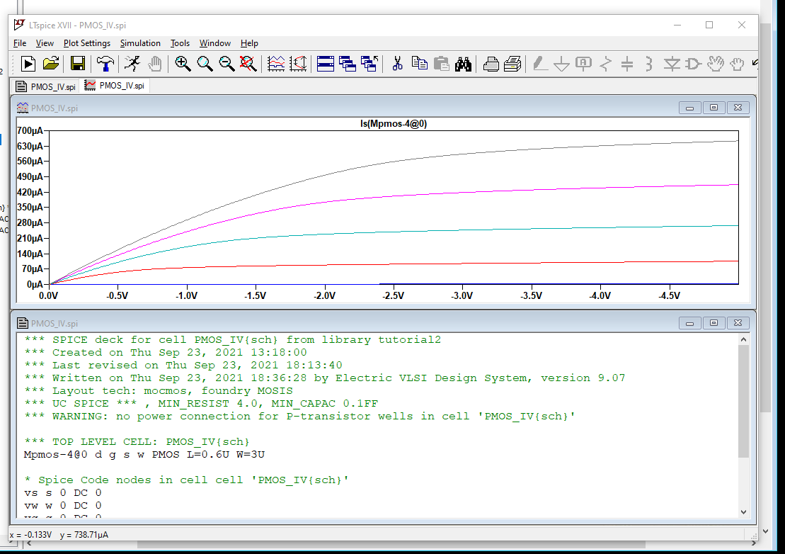
Figure 9. PMOS shematic simulation.
Discussion
In this lab we built two MOSFET's, NMOS, and PMOS. Both were built and coded in layout and schematic mode. In the above both the
layout and schematic agreed with each other. No DRC or well errors. However, the NMOS layout and schematic simulation did not
have the same output. The layout had a positive current and voltage. The schematic had negative current and positive voltage. I was
unable to find any mismatch and both had no DRC or well errors.