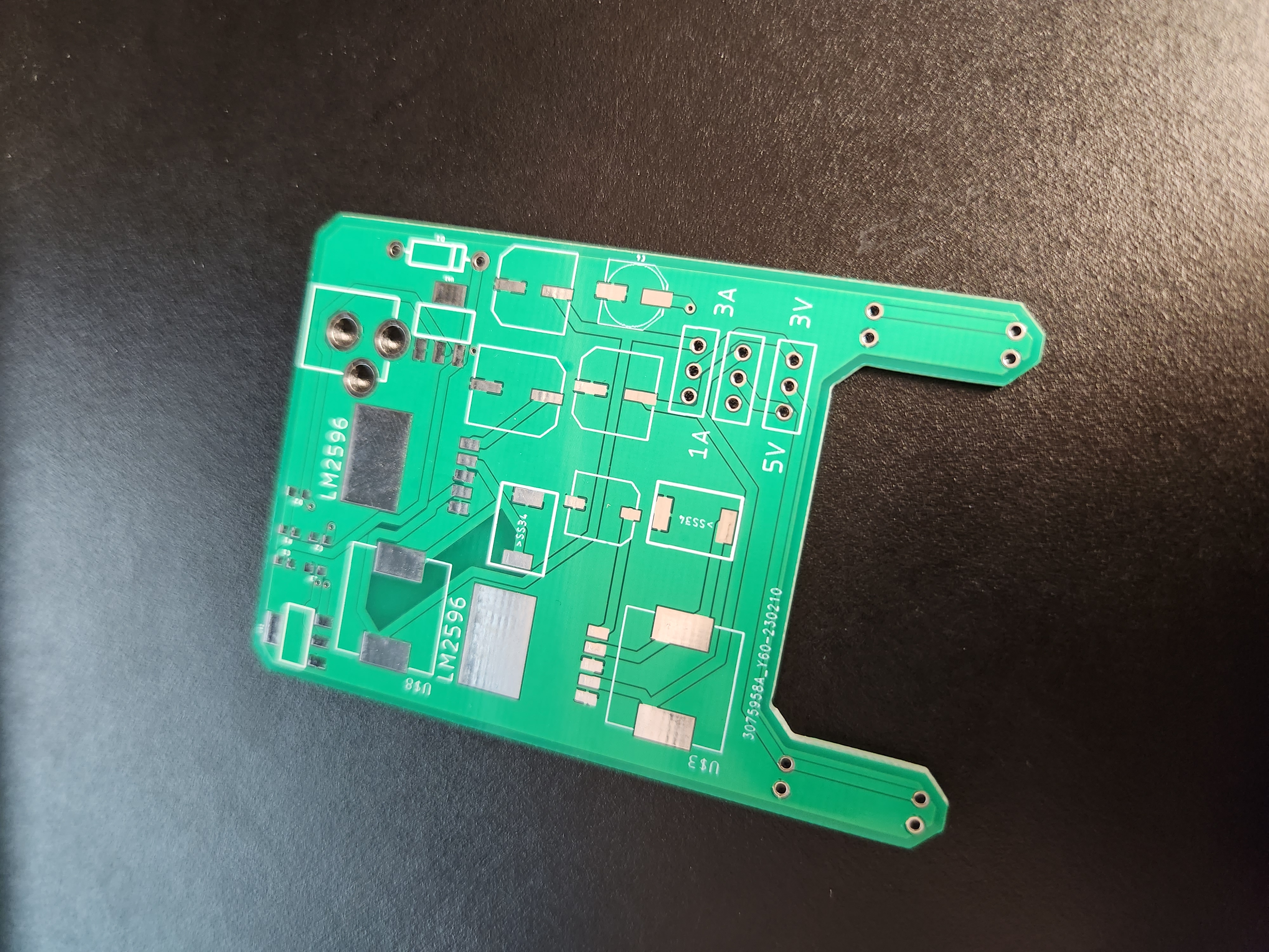
Power Supply circuit
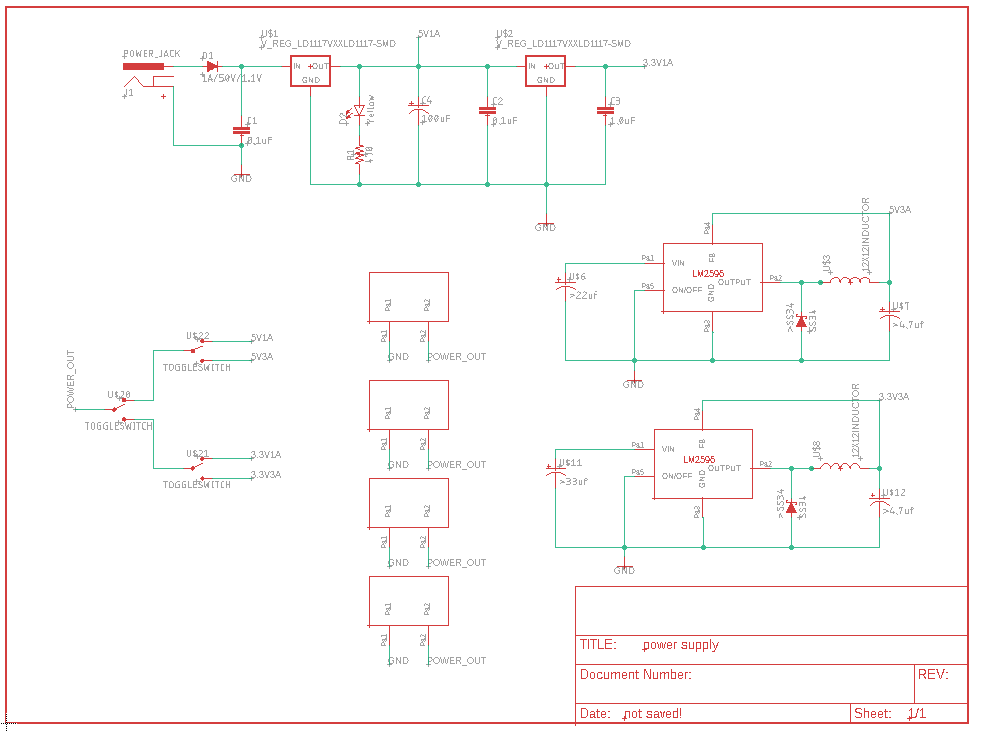
The following document contains reference information for a power supply circuit. The circuit is powered through a 9mm barrel jack and contains 3 switches which allow for the user to change both the voltage and current to 3.3v/5v and 1A/3A respectively. The shape of the board is designed to allow easy connection to a breadboard without obstruction of the central pin holes.

The
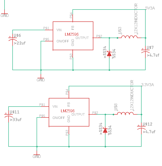
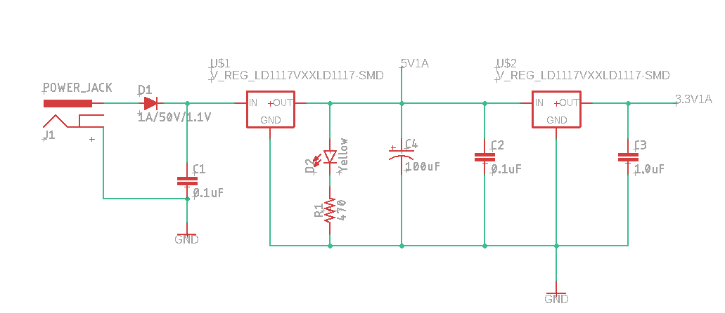
schematic consists of three main circuits. A 1A power circuit consisting of two
voltage regulators supplying 5v and 3.3v to the board. The two other circuits
are buck converters, each supplying 3A at 5v or 3.3v to the circuit.
The figure
below shows the entire schematic with the switches and board connector pins.
The switching circuit consists of two switches joined by another switch. The
center switch (U$20) will determine the voltage where the two connected to this
central switch (U$22 and U$21) decide the current.
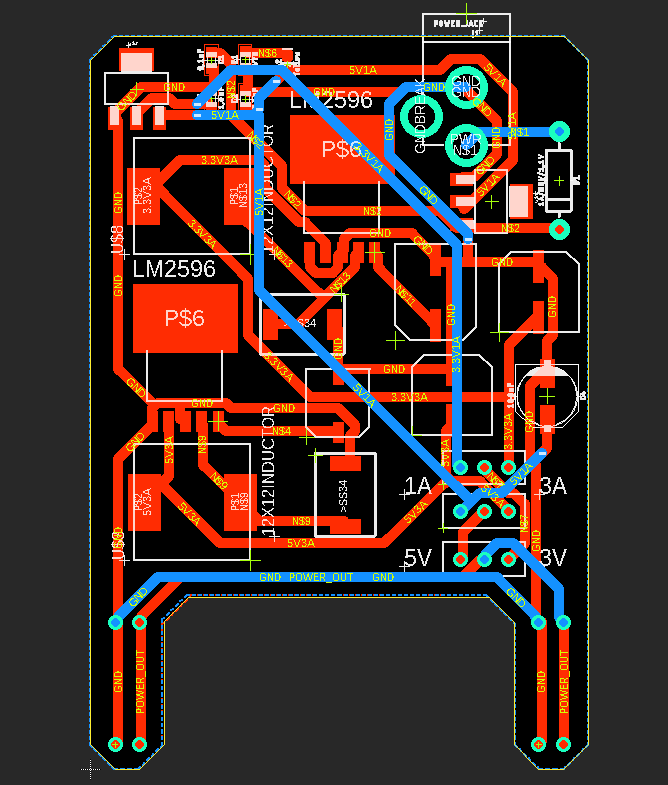
The board
design is arranged to be as compact as possible while maintaining
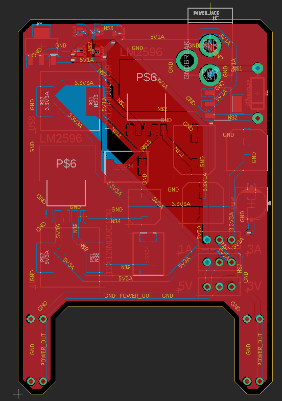
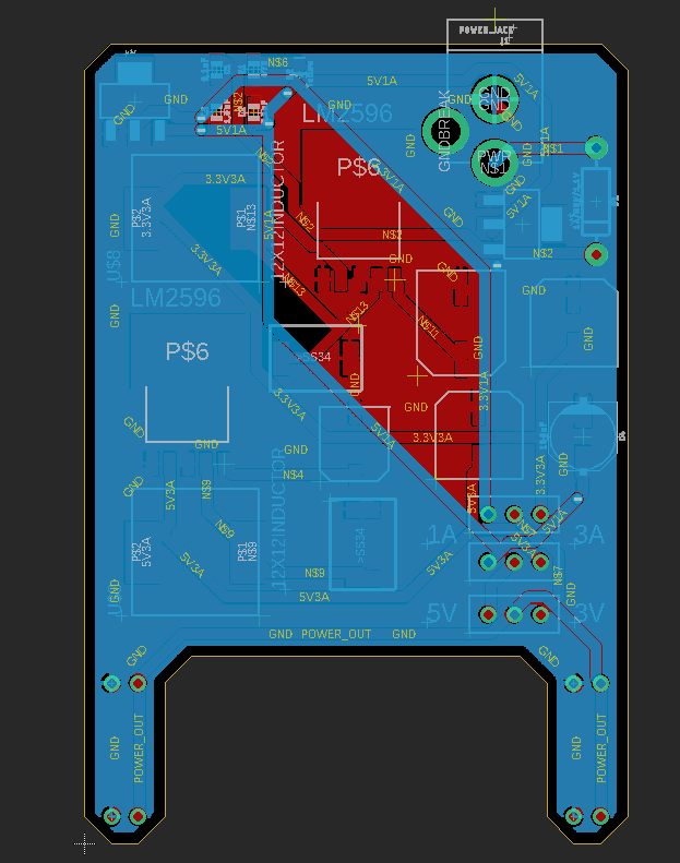
functionality. This board is made up of two layers (upper in red and lower in
blue). The ground connections are connected to a rat’s nest generated by Eagle
CAD after the traces were auto routed to reduce heat generated from joule
heating. The board has an onboard power indicator LED which is placed near the
9mm barrel jack. The switches are placed near the breadboard end of the board
for ease of access while prototyping. The switch nearest the pins controls the
voltage where the two pins above control the current. Both are clearly labeled
to indicate what switch does what.