ENGR337 Lab 2020 Spring
Lab 3 Filters and Amplifiers
Name: Ryan Ford
Email: rwford@fortlewis.edu
Introduction:
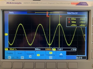
This lab required students to amplify a small signal (500 mVpp, 1Hz, 1
V DC offset) to the 0-5 V range. In the process, students were
challenged to observe and contrast results in noise, offset, and
attenuation of signals after circuit manipulation.
Materials and Methods:
Table 1: Materials List

Build the circuits as shown in the Lab 3 section on
yilectronics.com. Analyze the signals using an oscilloscope,
following instructions according to Lab 3. Perform
hand-calculations as required, and compare results with measured and
simulated data.
Results:
Task 1
Figure 1: Signal generated from (500 mVpp, 1 Hz, Offset: 1V)
Task 2
Figure 2: Signal from task 1, with AC coupling to remove the DC offset
Task 3
Figure 3: DC coupling of signal after adding 3.3 V DC voltage module
Figure 4: AC coupling of previous signal after adding 3.3 V DC voltage module
Task 4
Figure 5: Signal after adding low-pass filter to remove the 60 Hz noise
Task 5
Figure 6: Signal after adding a high-pass filter to remove the DC offset
Task 6
Figure 7: Signal with a 741 Op Amp and reference voltage
Figure 8: Signal after increasing the rail-to-rail power supply to 10 V
Figure 9: Signal after replacing the cheap 741 Op-Amp with a higher quality INA 128 PA Op Amp
Discussion:
Task 1: The generated signal matches the results displayed in the Lab 3 instructions, comfirming the results.
Task 2: After selecting the AC option, the DC offset was removed as expected.
Task 3: After adding the 3.3 V DC voltage, it was observed that the
signal was much noisier due to the noise from the wall outlet.
The AC coupling removed the offset from the signal, as opposed to the
DC coupling which did not.
Task 4: Adding a low-pass filter removed the 60 HZ noise. The noise reduction can be seen in the results.
Task 5: Adding a high-pass filter at the end removed the DC offset from
the signal. The difference in input and output can be seen in the
results.
Task 6: A 741 Op Amp was added to the circuit to amplify the
signal. A reference voltage was also added. Since the 741
Op Amp is not "rail-to-rail", the bottom output was cut-off.
Task 7: A solution to the previous problem was found by increasing the system voltage to 10 V, offsetting the signal by 5 V.
Task 8: Another Solution to task 6 was to replace the 741 op amp with a
higher quality device. The INA 128 PA op am amp was used in place
of the 741, and the DC offset was removed. The results show that
the solution was a viable option.