ENGR337 Lab 2020 Spring
Lab 1: LTSpice and Lab Report Preparation
Name: Ryan Ford
Email: rwford@fortlewis.edu
Introduction:
The purpose of this lab was to refamiliarize students with basic
concepts of electric circuit analysis, as well as introduce them to
analytical techniques using LTSpice.
Materials and Methods:
The materials used in this lab included 6 resistors, a breadboard, a multimeter, and LTSpice.
The first excercise was to build a circuit on a
breadboard and test voltages and currents in the circuit. Then, calculate
voltages and current using mesh current method. Finally, simulate the circuit
in LTSpice and compare results.
The following four excercise all employed the use of LTSpice for
circuit analysis. It was required that SPICE code be written to
generate all circuits. For the second circuit, time-delay was measured
between input and output voltages. In the third circuit, a DC
sweep was simulated for the input and output voltages. In the fourth
circuit, AC analysis was performed by simulating an AC sweep. In the
final circuit, DC pulses were used as input voltage to measure
time-delay in the circuit.
Results:
In Figure 1, below, a schematic of the given circuit for problem 1 is
displayed. Note that the voltages (red) and currents (green) are
labeled.

Figure 1: The circuit for problem 1
with labeled currents and voltages
The experimental and hand-calculated voltages for the circuit in problem 1 are shown in Table 2, below.
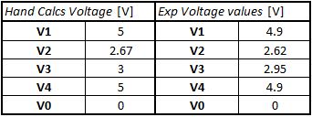
Table 2:
Experimental vs hand-calculated voltages in problem 1
The experimental and hand-caluclated currents for the circuit in problem 1 are shown in Table 3, below.
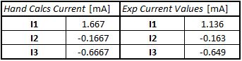
Table 3: Experimental vs hand-caluculated currents in problem 1
The SPICE code for problem 2
along with the generated graph are displayed below in Figure 2.
The time delay is shown as the horizontal distance between cursor 1 and
2, which resulted in 2.278 ms.
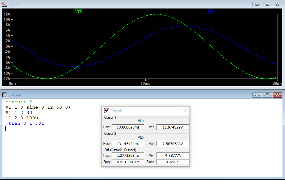
Figure 2: SPICE code for problem 2 along with graphical representation of time delay
The SPICE code for the circuit in problem 3 and the DC sweep is shown in Figure 3, below.
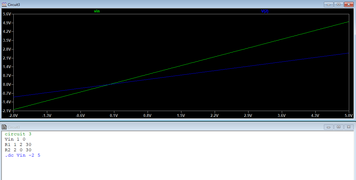
Figure 3: SPICE code and DC sweep for circuit in problem 3
The SPICE code and AC sweep for the circuit in problem 4 are displayed below in Figure 4.

Figure 4: SPICE code and AC sweep for cuircuit in problem 4
The SPICE code and time delay for the circuit in problem 5 are shown in
Figure 5. It can be seen that the measured time delay of the
output voltage is 19.6 ns.

Figure 1: The SPICE code and time-delay for
the circuit in problem 5
Discussion:
For problem 1, the experimental results closely match the values
obtained by calculation. Deviations in voltage and current are
due to tolereances from resistors.
For problem 2, the result for time-delay closely matched the value
displayed on the original lab instructions, confirming the results.
For problem 3, the resuts for the DC sweep were identical to the results in the lab instructions, confirming the results.
For problem 4, the results for the AC sweep were identical to the results in the lab instructions, confirming the results.
For problem 5, the time delay of the circuit was found to be 19.63 ns,
which is less than 1% different than the value shown in the lab
instructions. The results are close enough to confirm.