1. Introduction to ElectricVLSI (a voltage divider) 2. In this lab, students were introduced to the ElectricVLSI
software used for analog circuit fabrication. A series of tutorials set
up by Dr. Li, aimed at helping sutdents master the software, were
started and Tutorial one was completely finsished. In the tutorial
students designed a simple voltage divder as both a schematic and
layout as well as set up the correct preferences for fabricating CMOS
chips through MOSIS. This lab is the first in a series of labs designed
to allow students to complete all assigned tutorials.,
3. Materials
LTSpice
software (for simulation)
ElectricVLSI Software
Java (for running ElectricVLSI)
Methods Students
began the lab by downloading Java and ElectricVLSI to their computers
and followed the installation instructions, found in Tutorial One on
Dr. Li's website, to set up both programs. ElectricVLSI was launched
and the general preferences were changed to work for C5 semiconductors
fabricated through MOSIS. The analog technology was selected and the
scale for the design was set to 300 nm. The ElectricVLSI schematic was
saved and an "n-well" resistor was created following the specifications
laid out in Tutorial one. A layout was then created and the resistor
was translated from the scehmatic to the layout as stated in Tutorial
One. Both the layout and schematic were checked for errors before
proceeding. A second, identical resistor was placed in series with the
first resistor to create a voltage divider. The arcs (wires) were
labeled for simulation purposes. A .op code was implemented into the
schematic to measure both the Vin and Vout of the voltage divider using
LTSpice while in ElectricVLSI. The directory for LTSpice had to be
altered so the VLSI could intitate simulation correctly. Finally, the
layout of the voltage divider was updated and another .op code was
developed, according to Tutorial One, to measure the Vin and Vout of
the layout circuit. The final layout and schematic were doubled checked
for errors then saved
for reference in the upcoming tutorials.
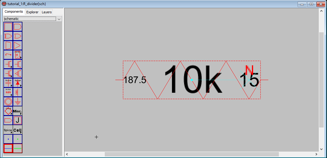
4. Results Figure 1. The initial resistor scehmatic designed in ElevtricVLSI in Task 1. This resisitor is an "n-well" type resistor.
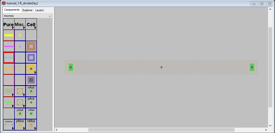
Figure 2. The initial resistor layout designed in Electric VLSI. This resisitor is an "n-well" type resistor.
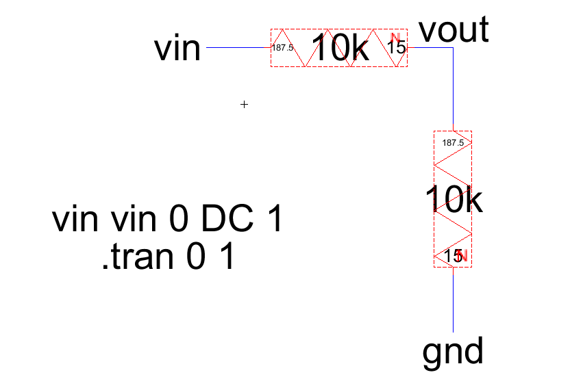
Figure 3. The completed
schematic for the voltage divider in VLSI and .op code used to
intialize the LTSpice simulation of the circuit.
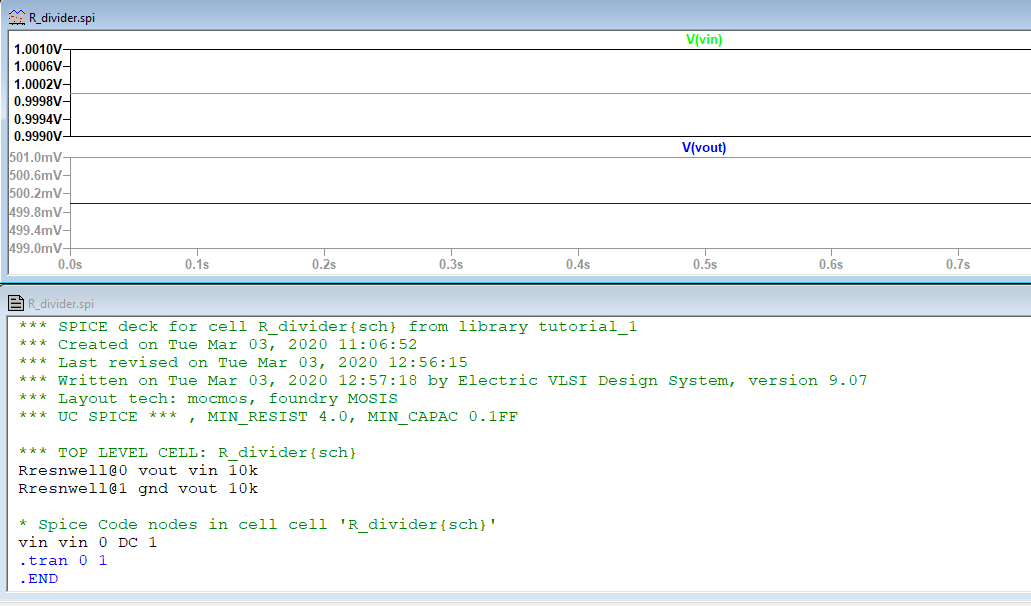
Figure 4. The LTSpice simulation of the voltage divider schematic.
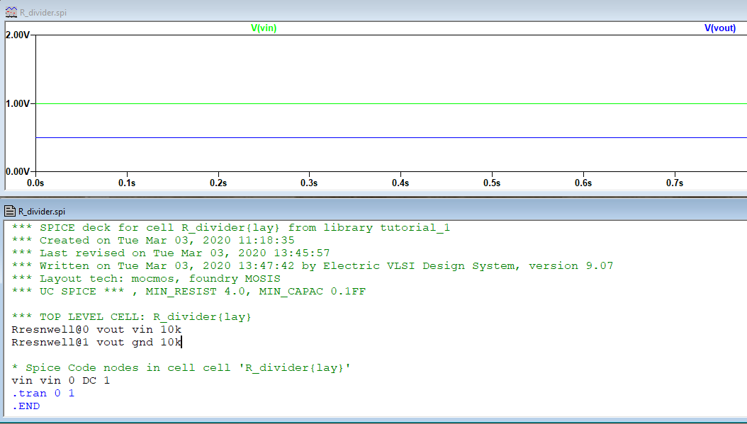
Figure 5. The complete layout
for the voltage divider circuit in VLSI and the .op code used to
initialize the LTSpice simualtion.
Figure 6. The completed LTSpice simulation of the VLSI layout.
5. Discussion This lab is the first is a series of labs designed to
have students complete all ElectricVLSI tutorials assigned by Dr. Li.
Tutorial One allowed students to familiarize themselves with the
software as well as set up the correct preferences for CMOS
fabrication. The lab was fairly straight-forward and the only point
students struggled with was defining the correct file path to allow
LTSpice to initialize from a .op code written in ElectricVLSI. Once
this issue was solved, the LTSpice simulation for both the schematic
and layout worked correctly and students were able to see how the
intial voltage was divided directly in half by the voltage divider
circuit. The tutorial served as a foundation for the next scheduled
tutorials and a nice introduction to a new software. The experience and
knowledge gained from this lab will be useful moving forward for
students in analog circuits because it will translate directly to the
final project for the course. Students will design their own analog
circuit utilizing transistors and will have to know how to use
ElectricVLSI to design it properly. The future labs will continue to
build on the base of knowledge gained from Tutorial One.