ENGR337 Lab 2020 Spring
Lab 3 xxxxxx
Name:
Orion Clay
Email: oeclay@fortlewis.edu

1. Filters and Amplifiers

2. In this lab students learned how to amplify and filter small signals using zener diodes, operational amplifiers, high pass filters, adn low pass filters. Students were given an initial AC signal and tasked with filtering various noises, removing DC offsets, and amplifying signals using the above mentioned methods.


3. Materials
Tektronix MSO 2022B Mixed Signal Oscilloscope and Probe
Multimeter probe (for circuit debugging)
Tektronix AGF1062 Arbitrary Function Generator
Bread Board
Two 100k Ohm Resistors
One 680 Ohm Resistor
2 and 5 Volt Zener Diodes
4.7 uF and 458 nF Capacitors
One 741 Operational Amplifier
0-5 Volt ADC Converter (For Power Supply)


**All cables necessary for taking measurements with the above devices were used in this lab.**

Methods
Task 1 required students to generate a 500 mVpp signal with a frequency of 1 Hz and DC offset of 1 V using the arbitrary function generator. The students used the oscilliscope to probe the signal. Task 2 had students remove the DC offset of the signal using the 'AC' viewing option
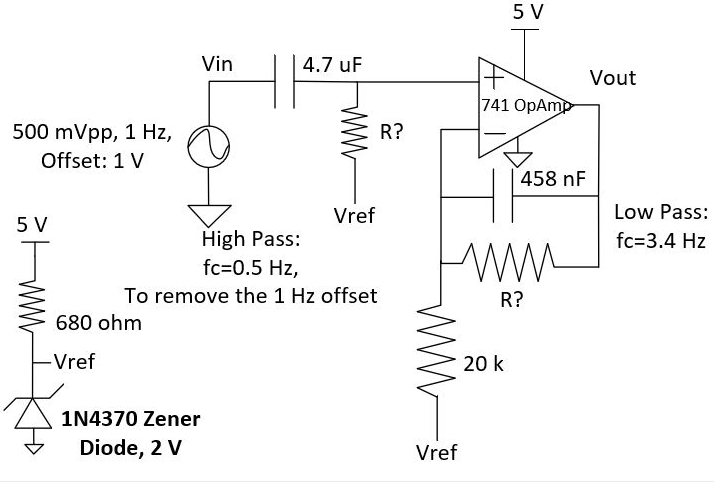
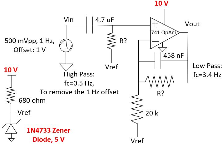
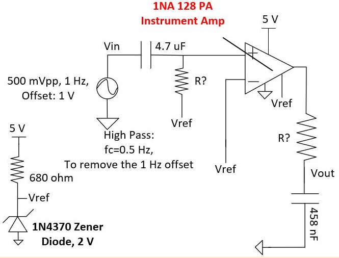
in the oscilliscope. Task 3 introduced a 60 Hz noise to the AC signal by inserting a 3.3 V power supply from an ADC converter powered by the wall outlet voltage. Students showed both the AC and DC couplings for the signal in screenshots. In Task 4, a low pass filter was constructed on a breadboard and used to remove the noise introduced by the wall outlet voltage. Students also calculated the appropriate resistance for the low pass filter given the cutoff frequency and capciatance. Task 5 had students create a high pass filter to remove the DC offset of the AC signal. The resistance of the high pass filter was calculated again with a given cutoff frequency and capacitance. The lab concluded with Task 6 where a 741 op amp and a zener diode  were incorperated into the circuit to amplify the AC signal. The task had three parts with the first part utilizing a 2-V zener diode, 5 V power supply, and a 741 op amp, then a 5-V zener diode, 10 V power supply, and a 741 op amp, and finally a 2-V zener diode, a 5 V power supply, and a 1NA 128 PA instrumentational amplifier.

4. Results


Figure 1. The sine wave input generated for Task 1 displayed in the oscilliscope.


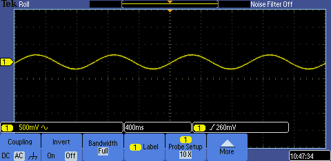
Figure 2. The sine wave input displayed with the 'AC' viewing option selected in the oscilliscope.


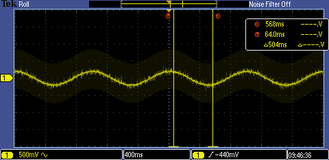
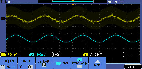
Figure 3. The DC coupling display for the noisy wall voltage input for Task 3.


Figure 4. The AC coupling display for the noisy wall voltage input for Task 3. Note: The AC coupling removes the DC offset.


Figure 5. The oscilliscope reading showing the noise removed by the constructed low pass filter.


Figure 6. The oscilliscope reading showing the DC offset removed by the constructed high pass filter.


Figure 7. The calculations done to find the resistances for Task 4 and 5.


Figure 8. The schematic for the circuit constructed in Task 6 a (provided by Dr. Li).


Figure 9. The input and output of the circuit from Task 6 a) in probed by the oscilliscope. Note: A 3 V zener diode was used in place of a  2 V  diode because no other 2 V diodes were available.


Figure 10. The schematic for the circuit constructed in Task 6 b (provided by Dr. Li).


Figure 11. The input and output of the circuit probed by the oscilliscope in Task 6 b.


Figure 12. The schematic for the circuit constructed in Task 6 c (provided by Dr. Li).


Figure 13. The input and output of the circuit probed by the oscilliscope in Task 6 c.
 
5. Discussion
This lab helped students learn how high pass and low pass filters can alter an input signal to the desired offset and noise reduction. The use of operational amplifiers was also demonstrated to students and the principle of signal amplification between voltage rails was introduced. Tasks 1 through 3 demonstrated to students how the an AC signal can be probed by an oscilliscope as well as how initial input signals can have a noise associated with them. Task 4 showed how a low pass filter can remove unwanted noise from an input signal and Task 5 presented how a high pass filter can remove a DC offset. The importance of using the correct resistance was shown in the calculations completed by students to ensure their low and high pass filters functioned effectively. Task 6 demonstrated the importance of having a large enough rail to rail voltage in an op amp so as to allow it to fully amplify an input signal as well as how low pass filters, high pass filters, op amps, and zener diodes can be utilized together to create a desired output signal.