
Time Delay: 10.3 ms
 .
.Vi = 10v
Vo = 2.4v
td 20.6us
| Part: | Count: |
| 100k, 1k, 100 ohm Resistors | x1 |
| 680p, 100p, 10p Farad Capacitors | x1 |
| Osciliscope | x1 |
| Signal Generator | x1 |
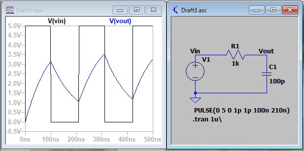
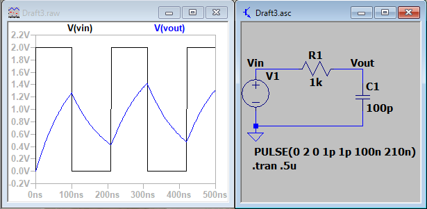
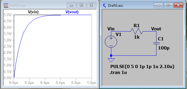
| Task 1 | Figure 1: Original Low Bandwidth Circuit | Figure 2: Pulse Voltage Dropped to 2V |
| | |
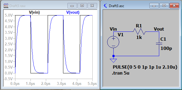
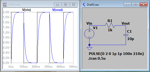
| Figure 3:: Ton and Tperiod set to 1u and 2.1u Respectively | Figure 4: Reducing Capacitor Size to 10p | |
| | |
| Figure 5: Reducing resistor to 100 ohm | ||
| ||
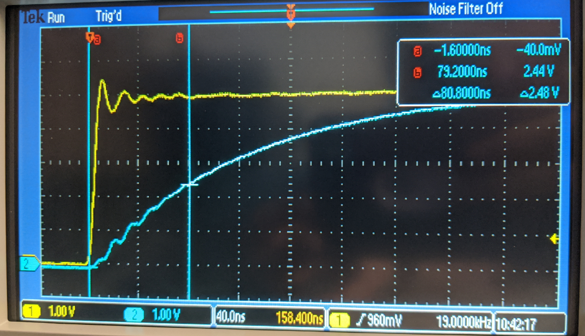
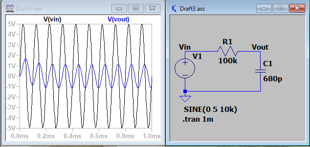
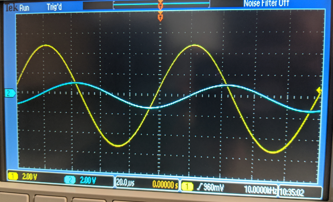
| Task 1.3: | Figure 6: Changing Frequency in Order to increase Bandwidth (Simulation) | Figure 7: Changing Frequency in Order to increase Bandwidth (Bread Board) |
| Time Delay: 10.3 ms | |
| Task: 2 | Figure 8: Simulated Time Delay | Figure 9: Measure and Calculated Time Delay |
| . Vi = 10v Vo = 2.4v td 20.6us | |
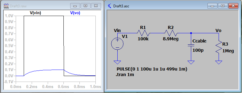
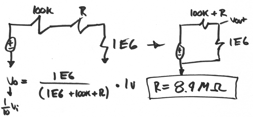
| Task: 3.1 | Figure 10: Simulated DC Cable | Figure 11: DC Cable Calculations |
| | |
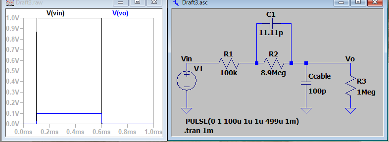
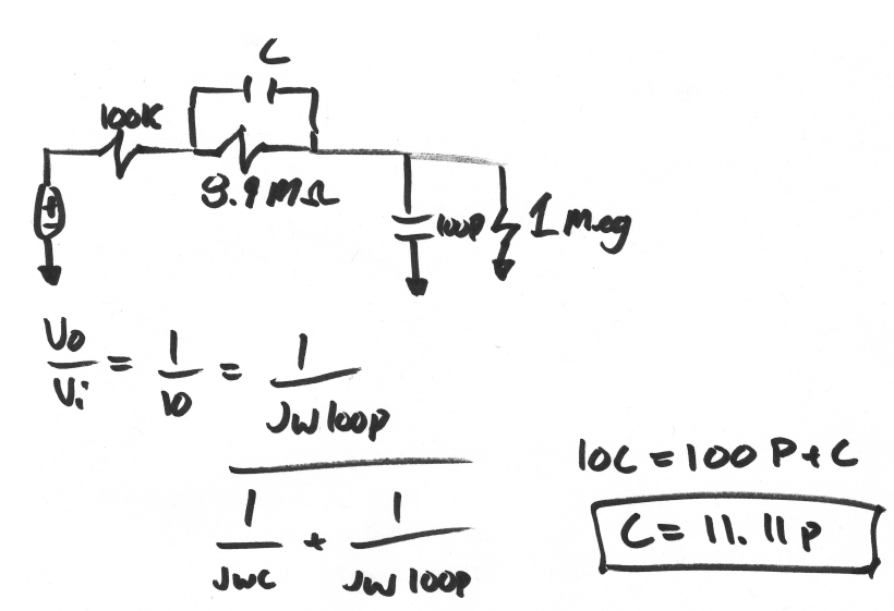
| Task: 3.2 | Figure 12: Simulated AC Cable | Figure 13: AC Cable Calculations |
| | |
| Task 3.3 | The scopes probe is set to 10:1. If changed to 1:1, values will be 1/10 of their actual value. |