This study will analyze the input and output of several types of rectifiers and DC regulators.

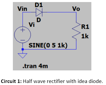
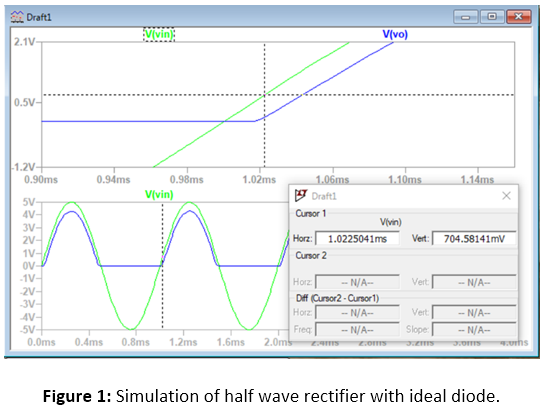
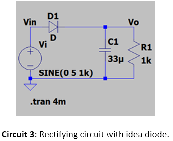
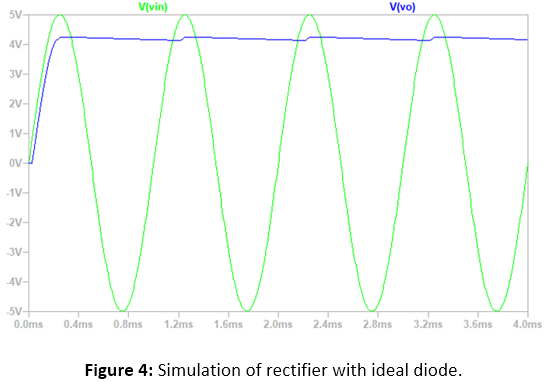
The rectifier shown in Circuit 1 was simulated with ideal
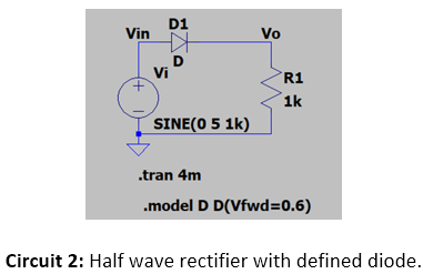
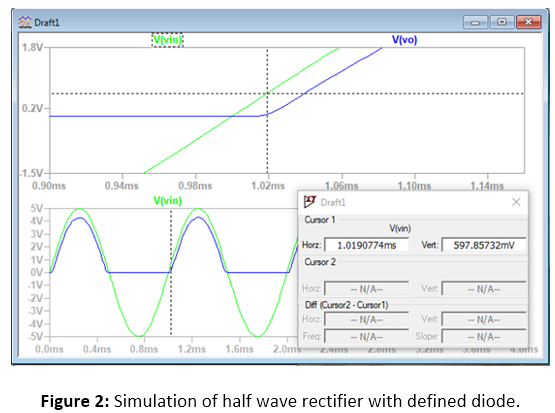
diodes and 0.6V built in voltage diodes (Figure 1,2). The same circuit was then
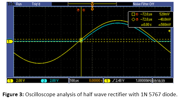
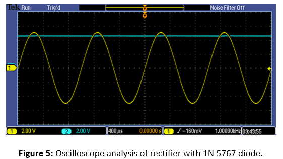
built on a breadboard with a 1N 5767 diode. The rectifier and smoothing circuit
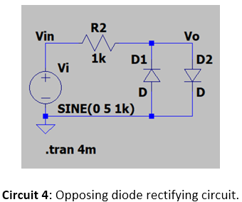
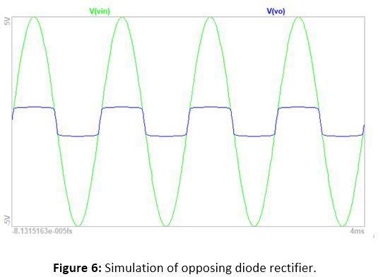
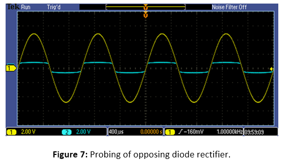
shown in Circuit 2 was simulated and built on a bread board. The opposing diode
rectifier in Circuit 4 was simulated and built on a bread board (Figure 6, 7).
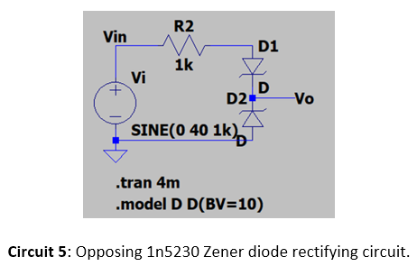
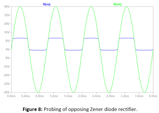
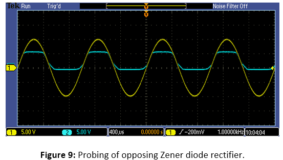
Similarly, the opposing Zener diode rectifier in Circuit 5 was simulated an built
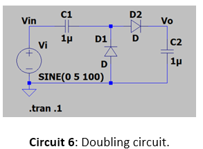
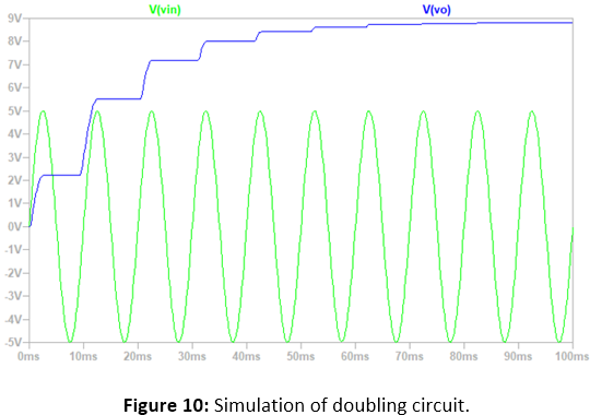
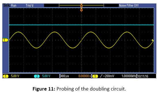
on a bread board (Figure 8, 9). The doubling circuit in Circuit 6 was simulated
and built on a bread board (Figure 10, 11).
Simulated response of Vo provided an AC current through Vin (Circuit
1). Built in potential was visually determined to be 0.7V (Figure 1).


The rectifying circuit with smoothing capacitor acts to rectify
the AC current and then smooth it with a large capacitor.


The opposing Zener diode rectifier was simulated in LTSPICE. The Zener diodes protect the circuit by clamping down as soon as the voltage goes above 10V.


The doubling circuit is simulated and built on a breadboard.
This circuit stores the charge created by both positive and negative voltages
and uses it to progressively step up the voltage.


