ENGR337 Lab 2020 Spring
Lab 3
Name: Nic Theobald
Email: nstheobald@fortlewis.edu
Noise Filtering Circuits
Introduction
This lab will cover the amplification of a small signal (500
mVpp, 1Hz, 1V DC offset) to the 0-5v range. Amplification will include the use
of operational amplifiers and instrument amplifiers
Materials and Methods
A sine wave with 500mV amplitude, 1 Hz frequency, and a 1V DC
offset was sampled by the oscilloscope set to DC couple. Due to DC
coupling, the signal is shown exactly as it occurs in the circuit
(Figure 1). The oscilloscope was then set to AC coupling and the
circuit is tested again (Figure 2). 60Hz noise was then added to the
circuit through the addition of a 3.3V DC power source. The circuit was
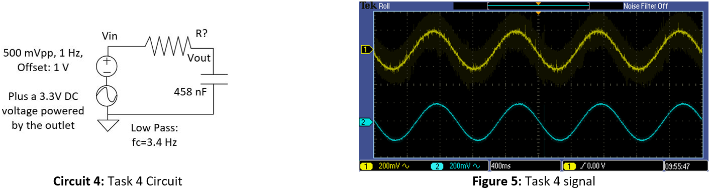
tested using both AC and DC coupling (Figure 3 & Figure 4). A low
pass filter (c_f=3.4 Hz,Ω=102.2kΩ,F=458nF) was then added to remove the
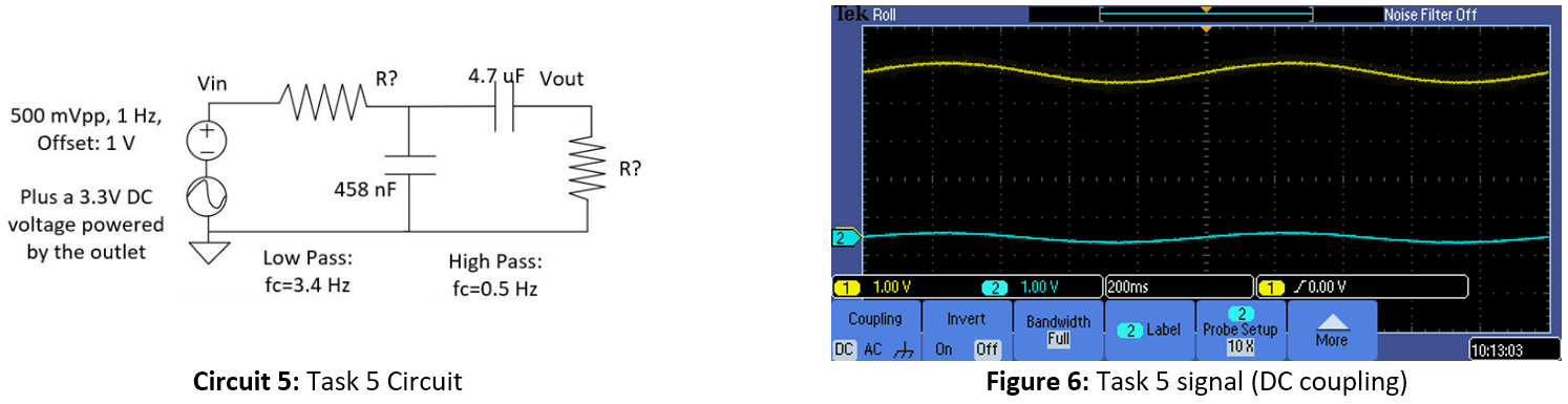
60Hz noise (Figure 5). A high pass filter (c_f=0.5 Hz,Ω=67.7kΩ,F=4.7μF)
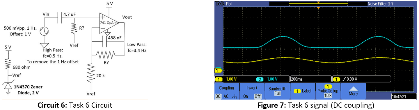
was then added to remove the DC offset (Figure 6). A 741 OP AMP was
added to the previous filter circuit in order to amplify the
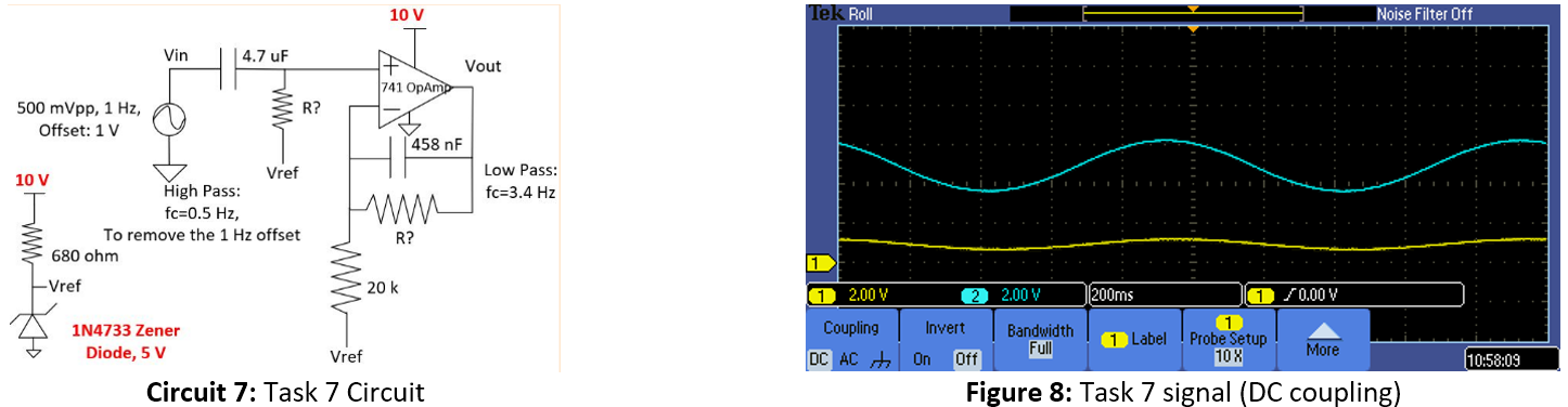
attenuated signal (Figure 7). The circuit from Task 6 was adjust so
that the reference voltage is set to 5V and the OP AMP top rail is
provided 10V. The circuit was tested using DC couple (Figure 8). A
instrument amplifier was added to the original high/low filter circuit
and Vo was probed using DC couple (Figure 9).
Results
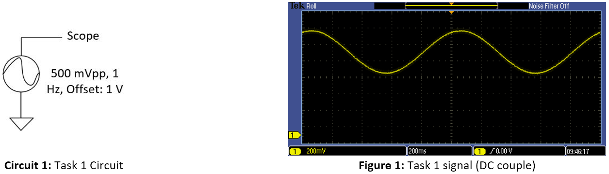
Task 1:
A sine wave with 500mV amplitude, 1 Hz
frequency, and a 1V DC offset was sampled by the oscilloscope set to DC
couple. Due to DC coupling, the signal is shown exactly as it occurs in
the circuit.
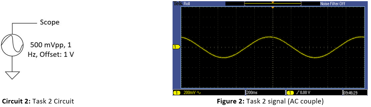
Task 2:
The same sine wave was sampled by the oscilloscope but with
AC coupling enabled. Due to AC coupling being enabled, the oscilloscope
automatically filtered out the DC offset.
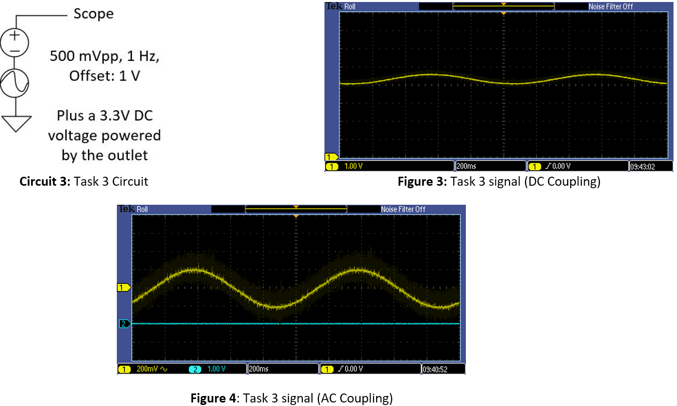
Task 3:
The same signal, from Task 1 and Task 2, was used
in this circuit but with the addition of noise with an amplitude of 3.3V and 60Hz
frequency. The oscilloscope is individually set to both coupling modes and is
used to test the signal output.
Task 4:
A low pass filter is added so that the previously added 60
Hz noise is filtered out. Given a cutoff frequency of 3.4 Hz, a 102.2 k resistor is used for the low pass filter.
Task 5:
A high pass filter is now added, before the low pass filter,
to filter out the DC offset. Given a cutoff frequency of 0.5 Hz, a 67.7 k resistor is used for the high pass filter.
Task 6:
A 741 OP AMP was added to the previous filter circuit in
order to amplify the attenuated signal. Because
the OP Amp was lower in quality, the bottom on the amplified signal was cut
off.
Task 7:
The circuit from Task 6 was adjust so that the reference
voltage is set to 5V and the OP AMP top rail is provided 10V. This adjustment
allowed the entire signal to be amplified.
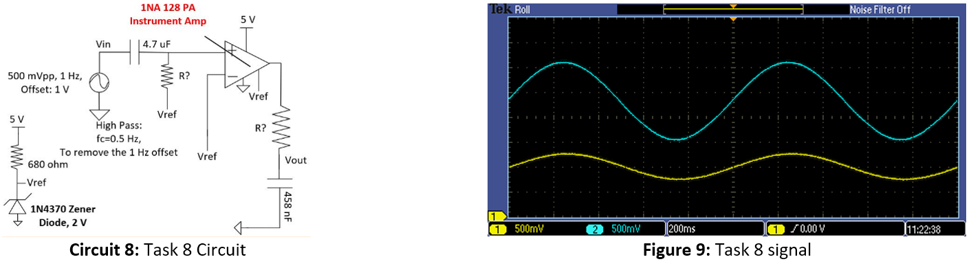
Task 8:
A instrument amplifier was added to the original high/low
filter circuit. The instrument amplifier is a higher quality component and is
able to amplify the signal with the original 5V without cutting off part of the
signal.
Discussion
Several passive and active
filtering circuits were shown in this study. It was shown that passive
filters cause amplitude attenuation and some types of active filters
distort the output signal.