ENGR 337 Lab 2020 Spring
Lab 06
Nic Theobald
nstheobald@fortlewis.edu
Electric VLSI Tutorial 1
Introduction
This Lab covers the operation of the VLSI software and the design of a simple voltage divider; using semiconducting material in multiple different orientations, resistive material can be produced.
Materials
|
Computer |
1 |
|
LTSPICE |
1 |
|
Electric VLSI |
1 |
|
Your Brain |
1 |
|
Some Patience |
1 |
Abbreviated Methods
Electric VLSI uses files that contain schematic, layout, and other things under one program name, cells and libraries. To start a new project a new cell must be made. This lab used 300nm technology. With a new cell, a schematic and layout can be created. On the Schematic, a n-well resistor is selected and dropped into view. Dimensions of the resistor are set to 15 width and 187.5 length. On the layout, a n-well resistor is added to the view. Dimensions are set to L = 187.5, W = 15. Another Resistor is added to both schematic and layout and they are wired together using an ARC. LTSPICE is then used to simulate and prove the circuit works.
Results
The simulated circuit is shown using the LTSPICE graphic interface.
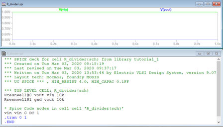
Figure 1: LTSPICE output
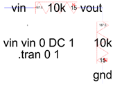
Figure 2: Electric VLSI Schematic
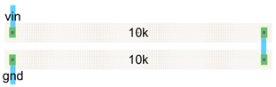
Figure 3: Electric VLSI Layout
Discussion:
Electric VLSI was used to design and simulate a simple voltage divider. Electric VLSI proved especially useful in its ability to recognize mistakes in the design. Several techniques were used to recognize mistakes. Built in error checking tools were used to find mistakes in the schematic and layout. LTSPICE was used to make sure the circuit performed as expected.