1. Filters and Amplifiers
2. Introduction
The purpose of this lab is to construct circuits that are able to amplify a small signal, 500 mVpp, 1 Hz, and 1 V DC offset to the 0-5 V range. The 0-5 V range is an optimal range because we are able to assume the power supply for the system is 5 V. The Dynamic range of the Analog-Digital Converter (ADC) is 0-5 V. The is the signal we are matching by amplifying the small input signal.
3. Materials and Methods
The first step in this lab was to produce a sine wave signal with 500mVpp, 1Hz, and 1 V DC off set with the signal generator. This signal was then observed on the oscilloscope in both DC and AC modes. The next step was to build a circuit was built on a bread board and add a 3.3 V DC voltage from the 3.3-5V DC module to the sine wave that we were all ready generating. After this noise was added to the signal, the next step was to filter it out. The original circuit was modified by adding a Low-Pass filter to remove the 60 Hz noise added to the circuit. The next step was to add a High-Pass Filter to the circuit to remove the DC offset from the signal. The cutoff frequency was desired to be 0.5 Hz and the value of the capacitor was 4.7 uF. The next step was to add gain to the signal. This was done by using a 741 Op Amp and adding 2 V DC offset as the reference voltage. This was provided by a 2 V zener diode and a 680 ohm resistor. The next step was to improve the signal gain by increasing the rail to rail voltage seen by the 741 OP Amp and increasing the reference voltage to 5 V. This does provided the desired signal gain to the circuit, but with an in creased voltage. The next step is to do try and produce the replicate the signal increase with only 5 V rail to rail voltage being delivered to the Op Amp. In the next step the 741 Op Amp was replaced with a 1NA 128 PA Instrument Amp.
4. Results

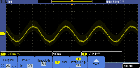
Figure 1: The 500 mVpp, 1 Hz, 1 V DC sine wave signal being observed on the oscilloscope in DC mode.

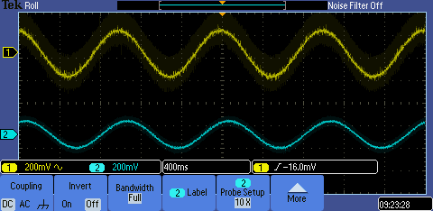
Figure 2: