1. Electric VLSI Tutorial 3
2. Introduction
The goal of this lab was to continue completing the Electric VLSI tutorials found on Yilectronics.com. This section lead into creating componants that condense the layouts and schematics into usable pieces. An inverted was created using our NMOS and PMOS from tutorial 2. The tool box is being expanded and we are using previously constructed componants. The ephesis seems to be on building a foundation and showing the efficiency of resuse.
3. Materials and Methods
Electric VLSI was the main program used for laying out the MOSFETS while LTSpice was used for circuit simulation.
4. Results

Figure 1. Schematic layout of inverter and component created

Figure 2. Inverter model connected to wires and Spice code for simulation

Figure 3. Vin vs Vout simulated using figure 2.

Figure 4. Inverter layout converted to a model. Spice code for simlation
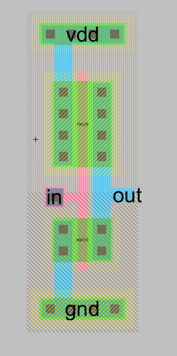
Figure 5. Internal Layout of inverter

Figure 6. LTspice simulation of Vin vs Vout. Simulated using spice code in figure 4
5. Discussion
This tutorial expanded our knowlege of how to use Electric VLSI. Most notibly the reuse of previous schematics and the conversion to a coponant added to a library. The simulated results were as to be expected. One unforseen outcome was when I incorrectly changed the width of the PMOS, it illustrated the effect it has on the vin vs vout curve. Cool to have a renforcment of why width of the wells is chosen.