4. Results:
Task 1:
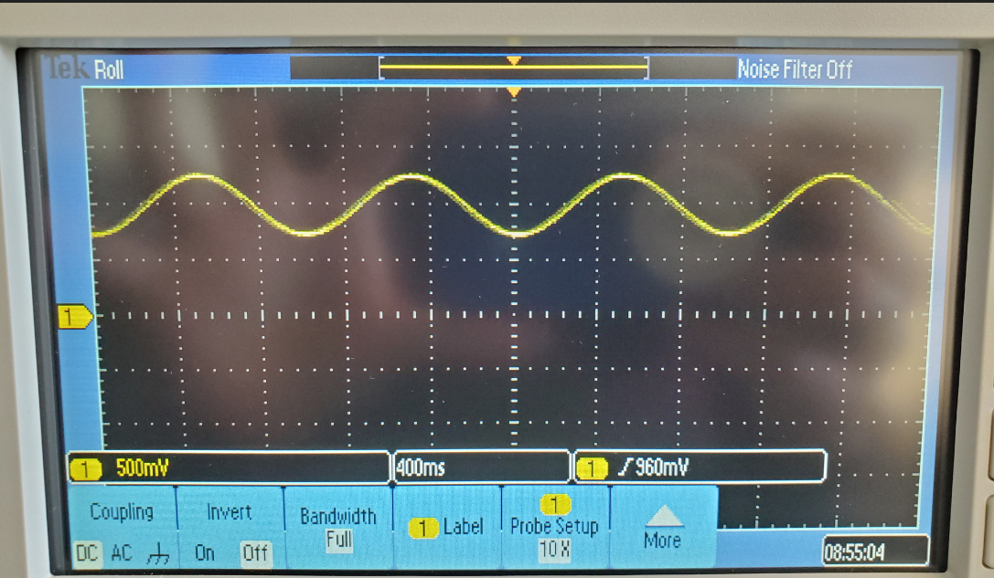
Figure 1. 500 mVpp, 1Hz, 1V DC offset provided by function generator
Task 2:
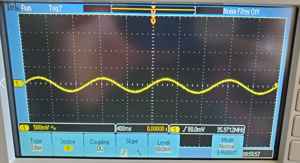
Figure 2. DC offset removed using oscilloscopes AC Coupling
Task 3:
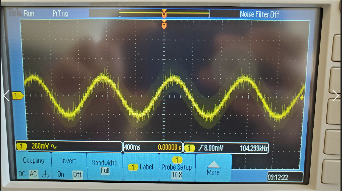
Figure 3: Noise added to signal from 3.3V ADC
Task 4:
R was found by solving the equation:
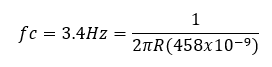
R was found to be 102kΩ. A 100kΩ resistor was used in the circuit
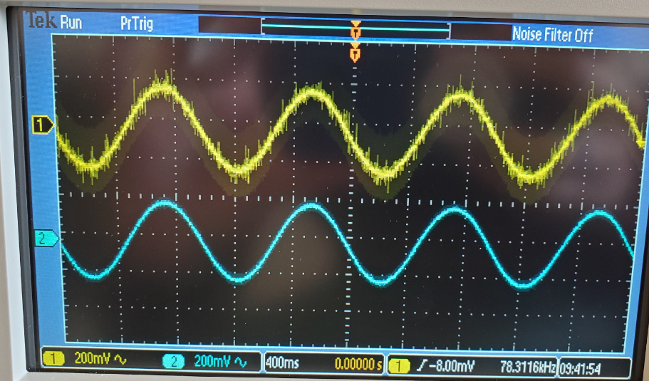
Figure 4. Lowpass filter added, noise removed from the signal
Task 5.
The lowpass filter's R was the same as task 5. The highpass' R was found to be 67.7kΩ by solving the equation:
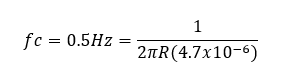
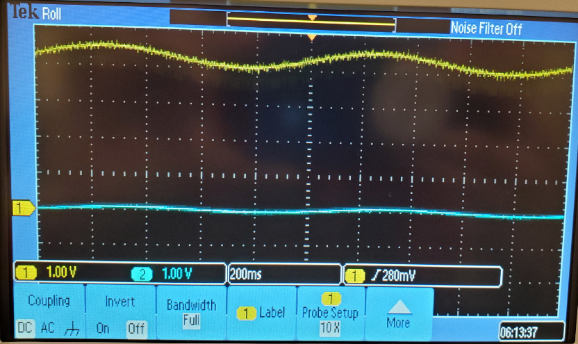
Figure 5. High pass and lowpass filters added in. Noise and DC offset removed however, the signal is attenuated.
Task 6.
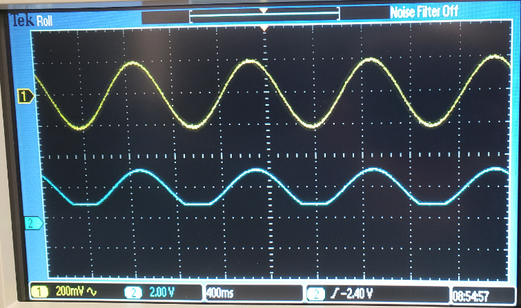
Figure 6. Op Amp cuts off upper end of signal due to low quality of componant.
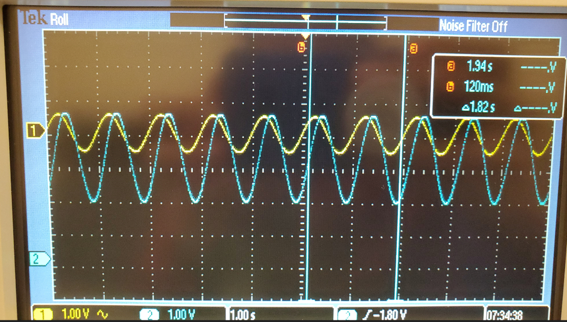
Figure 7. 10V power on Op Amp allows for full swing of amplification
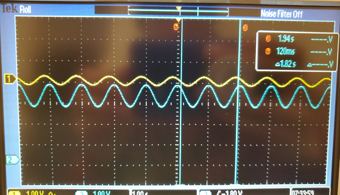
Figure 8. Using instrument amp we can amplify the signal while using 5V rail to rail.
5. Discussion
This lab took the concepts we have been learning in lecture and applied them to physical circuits. It illustrated how noise is introduced from the wall socket and the importance of quality of componants as well as how to work around them. The oscilloscope is a powerful tool for circuit analysis.