ENGR337 Lab 2 2020 Spring
Lab 2 More Spice and the Compensation Probe
Name: Jesse Duran
Email: Duranijesse@gmail.com
1. Title More Spice
and the Compensation Probe
2. Introduction
During this lab we were tasked with building low pass filters and
testing them in the lab using a function generator and an
occsilloscope. The circuits were compared to LTSpice simulations and hand calculations.
3. Materials and Methods
Materials
|
| Oscilloscope |
Function generator
|
100k ohm resistor
|
1k ohm resistor
|
100p capacitor
|
680p capacitor
|
Bread board
|
Students followed instructions layed out on Yilectronics.com for tasks 1-3.
4. Results:
Task1
Task 1.1
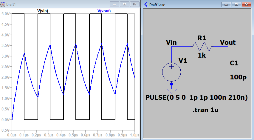
Figure 1. Vout doesn't reach the voltage of Vin due to limited bandwith of the circuit.
Task 1.2
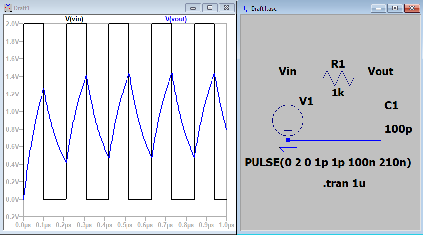
Figure 1.2a. Vout does not reach full voltage of
Vin. Changing from 2v to 5v did not increase the bandwidth of the
circuit.
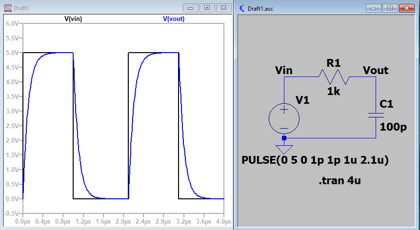
Figure 1.2b. Vout now reaches the full voltage of
Vin. This is due to the reduced frequency allowing the bandwidth to
have time to reach full voltage.
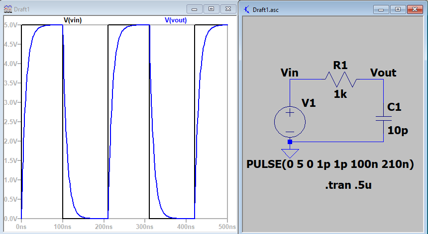
Figure 1.2c. Vout reaches full voltage of 5v. Reducing the cap to 10p allowed for full saturation.
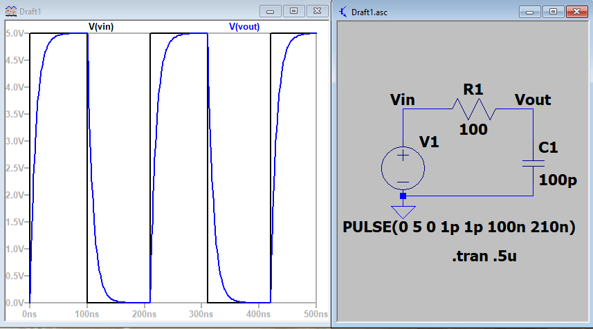
Figure 1.2d. The capacitor reaches full charge due to reducing the resistor to 100ohm.
Task 1.3
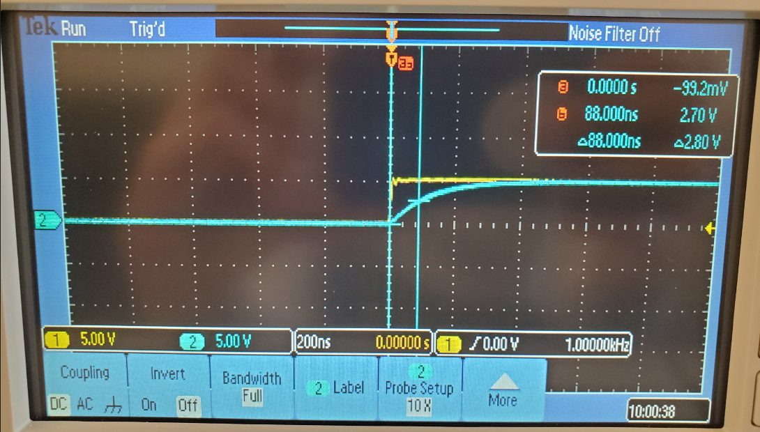
Figure 1.3. Time delay mesured on oscilloscope from
real circuit. Square wave provided by function generator. (could have
shortened time scale to get more accurate td.)
Task 2
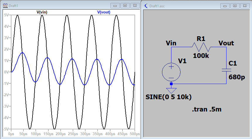
Figure 2. Simulated circuit of Vin vs Vout using LTSpice
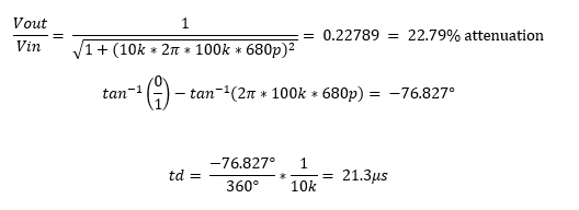
Figure 2b Calulation of Timedelay and attenuation
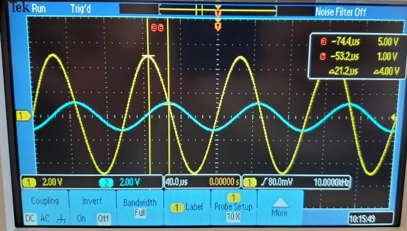
Figure 2c. Oscilloscope measurement of time delay.
|
Simulated
|
Calculated
|
Measured
|
Vin/Vout
|
.2537
|
0.2289
|
.24
|
Time Delay
|
20.5 μs |
21.3 μs |
21.2
|
Table 1. Comparison of simulated, Calculated and Measured values of Vin/Vout and Time delay.
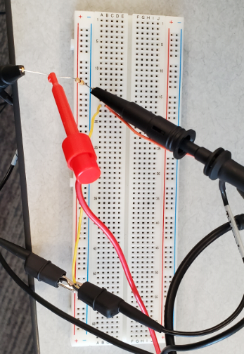
Figure 2d. Physical circuit
Task 3
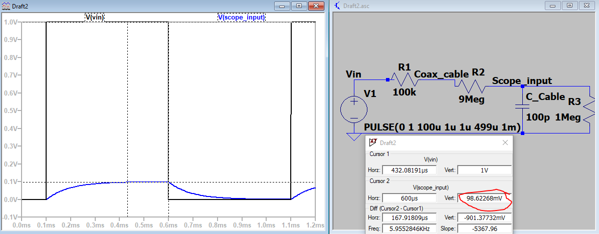
Figure 3.1 Compensation probe simulation with 9Meg ohm resistor.
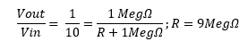
Figure 3.1b. Calulation for R to make 10x attenuation
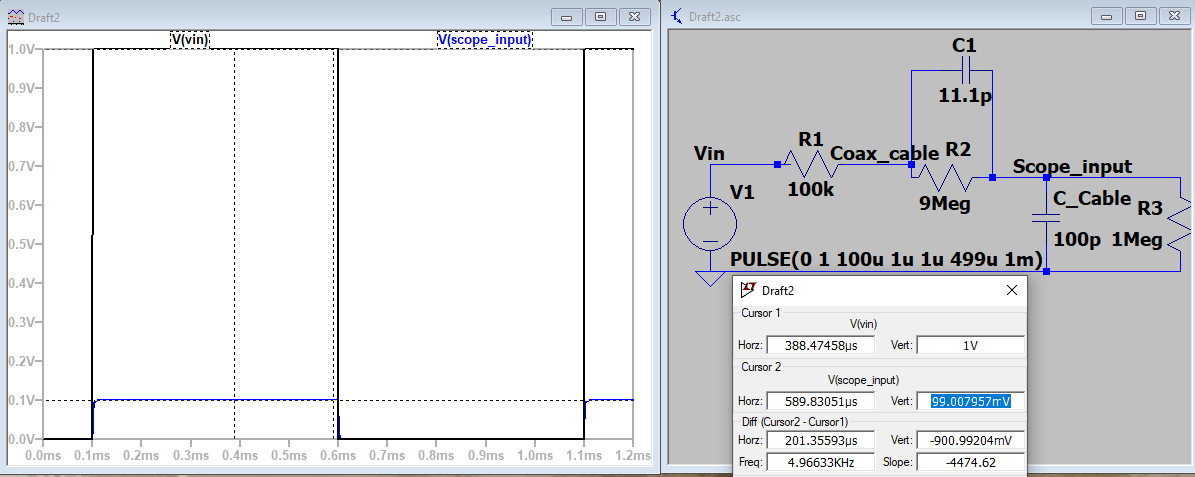
Figure 3.2 Compensation probe simulation with
calulated capacitor added in. 10x attenuation was nearly achieved.
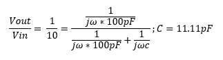
Figure 3.2b Calculation for unknown capacitor value
5. Discussion
During this lab students learned how to manuipulate
capacitor and resistor values to make low pass filters. Additonally
they became more familar with the compensation probe used for the
oscilliscope.
3.3
The type of scoped used was a 10x. Changing it
to 1:1 reduces the input voltage read to be equal to the output probe,
it is no longer amplified.