ENGR337 Lab 2020 Spring
Lab 6 Introduction to ElectricVLSI (a voltage divider)
Name: Donovan Birky
Email: dkbirky@fortlewis.edu
1. Title - Introduction to ElectricVLSI (a voltage divider)
2. Introduction
The goal
for this lab was to get an introduction to semiconductor layout design
with ElectricVLSI by designing a voltage divider.
3. Materials and Methods
All that was needed for this
lab was the ElectricVLSI software. This software is unique in that it
allows us to simulate the circuits designed in the software directly in
LTSpice. For this lab, the software first had to be configured to run
the simulations in the LTSpice program. The program also had to be
configured to run analog analyses, with the proper C5 semiconductor
layout specified. With these settings applied, a voltage divider
circuit was created in the schematic view using two N-well resistor
components wired together. The simulation was conducted by supplying a
SPICE code specifying a transient analysis for 1 second, and a 1V DC
power supply. Then the circuit was also created in the layout view,
which shows the actual N-well pad configuration. These were wired up,
and the same SPICE code was used to run the simulation.
4. Results
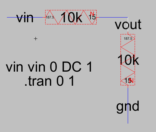
Figure 1. Schematic view of the voltage divider cricuit.
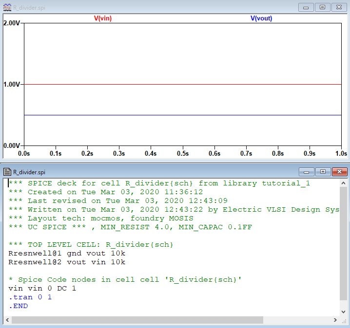
Figure 2. Simulation for the schematic view run in LTSpice.

Figure 3. Layout view of the voltage divider circuit.
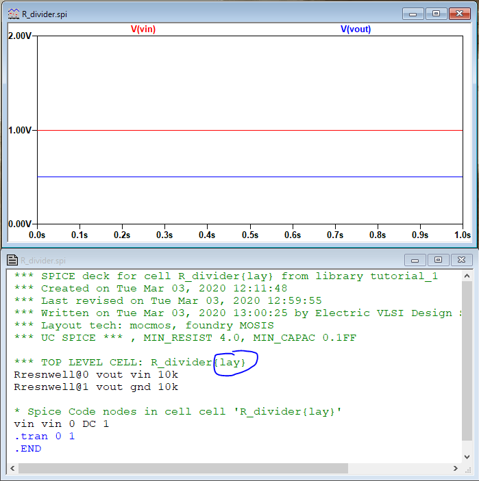
Figure 4. Simulationfor the layout view run in LTSpice.
5. Discussion
The results show that both the schematic simulation and the layout
simulation run and the results are what you expect from a voltage
divider circuit. This lab was a good introduction to learn how the
ElectricVLSI prgram works, with introduction to both the schematic and
layout views of the voltage divider circuit. One important lesson
learned is to check for errors often, as well as check and make sure
that the components in the layout view match the components in the
schematic view using the Network Consistency Checking (NCC) tool.
Overall, the lab was successful and will prepare us for harder circuit
layouts that will need to be conducted in the future.