ENGR337 Lab 2020 Spring
Lab 3 Filters and Amplifiers
Name: Donovan Birky
Email: dkbirky@fortlewis.edu
1. Title - Filters and Amplifiers
2. Introduction
The goal
for this lab was to use passive filters to create high and low pass
filters to remove the DC offset and the noise of a signal, then use an
amplifier to amplify the signal to a readable amplitude.
3. Materials and Methods
The first task was simply to observe a
signal generated from the signal generator (a sine wave: 500 mVpp, 1
Hz, 1V offset) on the oscilloscope using just the DC mode on the
oscilloscope. The second task was to utilize this same signal and
observe it using the AC mode on the oscilloscope. Now for the third
task the AC to DC converter was used to provide a 3.3V noisy DC voltage
to the signal and observe it on the scope. The fourth task was to use a
resistor and capacitor (passive filters) to design a low pass filter to
get rid of the noise being put on the signal. This required a 458 nF
capacitor, and the resistance was calculated based on a cutoff voltage
of 3.4 Hz. The input noisy signal and the output signal were observed
on the scope. The fifth task was to add a high pass filter using
a 4.7 micro farrad capacitor, and the resistance was chosen to
give a cutoff frequency of 0.5 Hz. The input and output were observed
on the scope. The result of task five should show that the signal is
being attenuated because of the passive filters. Task six now uses a TI
741 Op amp to amplify the signal. A non-inverting configuration is
used, and a 2V reference voltage is created using a zener diode
connected to a 680 ohm resistor and a 5V power supply. The input and
output are observed on the scope. Task seven aims to fix the problems
with using the cheap 741 op amp by using the 1NA 128 PA instrumental
amplifier instead. Again, the input and output are shown on the scope.
4. Results
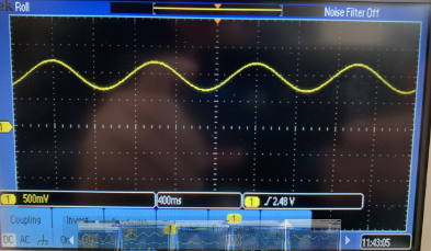
Figure 1. Signal being observed on the DC mode of the oscilloscope.
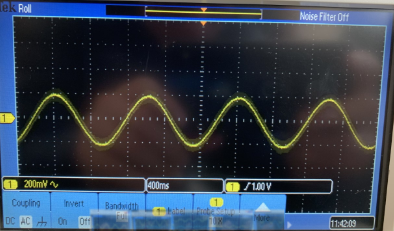
Figure 2. Signal being observed on teh AC mode of the oscilloscope.
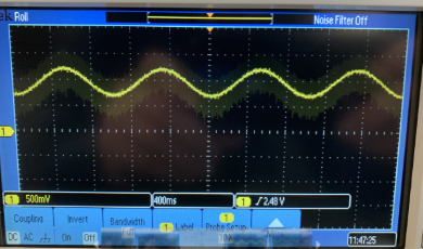
Figure 3. Signal with the addidion of the 60Hz noise.
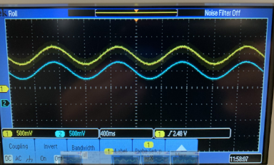
Figure 4. The input noisy signal (yellow) and the filtered output (blue).

Figure 5. The completely filtered output (blue) with DC offset and 60Hz noise removed.
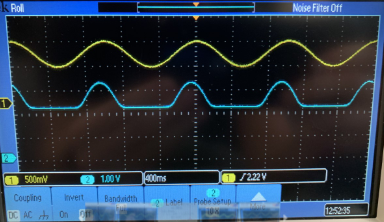
Figure 6. The filtered and amplified signal using the 741 op-amp.

Figure 7. The filtered and amplified signal using the 1NA 128 PA. Note the change in scale for the two signals.
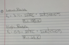
Figure 8. Calculations for the high and low pass filters.
5. Discussion
The first two tasks showed that the AC mode on the
oscilloscope can effectively remove the DC offset on a signal. This AC
mode would not want to be used for our analysis, because we want to see
how effectively we can create our own filters to remove these signals.
The next three tasks showed that a noisy signal could be generated, and
the noise plus the DC offset could be removed using a low and high pass
filter, respectively. This required calculation of the resistors needed
for the appropriate cit off frequency, which is shown in Figure 8.
However, the passive filters do not do this in the most efficient way
because they cause some attenuation. This can be corrected using an
op-amp, which task six showed that the 741 op-amp is not ideal for. The
final task utilized the instrumental amplifier, which resulted in a
nice clean signal removed of noise and DC offset. Overall, the lab was
helpful in showing how to manipulate signals and get a nice, clean
amplified signal in the end.