The goal for this lab was to refamiliarize ourselves with using LTSpice and performing circuit analysis on a breadboard.
3. Materials and Methods
This lab required LTSpice software for simulations on five different circuits. The first circuit was also built on a breadboard utilizing 3 2k ohm resistors and 3 3k ohm resistors. The circuit was powered up utilizing a dc voltage converter to deliver a dc voltage of 5V. Voltages and currents were recorded utilizing a multimeter. For the measured values, the mesh current method was utilized to solve for currents and voltages. Finally, the simulation of the circuit was run in LTSpice. These 3 values for each parameter were recorded in a table.
Circuit 2 required measurement of time delay and amplitude using simulation. Circuit 3 and 4 did not require calculation or testing on a breadboard. These circuits were simulated in LTSpice. The last circuit required calculation of the time delay, which was then compared to the simulated result found from LTSpice.
4. Results
Table 1. Calculated, simulated, and measured voltage and current values for circuit 1.


Figure 1. Simulation for circuit 1.
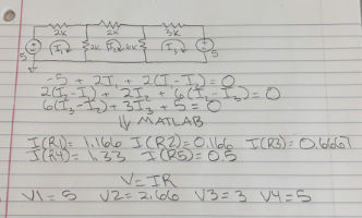
Figure 2. Calculations for circuit 1.
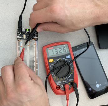
Figure 3. Measurement for circuit 1.
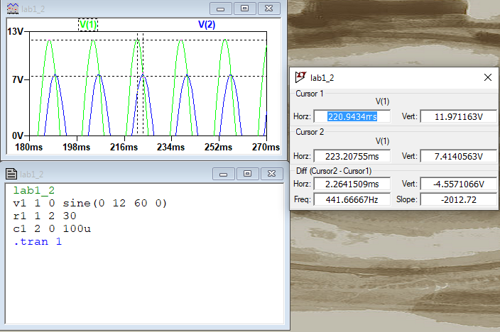
Figure 4. Simulation for circuit 2. Analysis showed an amplitude attenuation of 0.62, and a time delay of 2.26ms.

Figure 5. Simulation for circuit 3.

Figure 6. Simulation for circuit 4.

Figure 7. Simulation for circuit 5.

Figure 8. Calculation for circuit 5.
5. Discussion
The results in Table 1 show that the calculation, simulations, and measured values for the voltages and currents in circuit 1 matched up well, with only slight descrepencies between the measured values and those found in simulation. This is likely because of the internal resistance present in the circuit as well as in the multimeter used to measure these values.
Circuit 2 was used to practice measuring time delay and amplitude attenuation, which was 2.26ms and 0.62, respectively. The rest of the circuits analyzed utilized different techniques in LTSpice which were important to become refamiliarized with. The last circuit required calculation of the time delay in the circuit, which matched what the simulation predicted well. Overall, the lab was successful in becoming refamiliarized with circuit analysis.