ENGR337 Lab 2020 Spring
Lab 6: Layout an N-Well Resistor and Voltage Divider in ElectricVLSI
(Tutorial 1 in Tutorial Series)
Name: Audra Benally
Email: albenally1@fortlewis.edu
1. Title: Tutorial 1: Introduction to ElectricVLSI (a voltage divider)
2. Introduction: The goal of this lab was to learn how to use
ElectricVLSI by designing a voltage divider. The easy step-by-steb
tutorial showed how to change properties and access different features
and even set up LTSpice for circuit simulation. Once the circuits were
created the simulation on LTSpice showed the voltage divider circuits
working properly.
3. Materials and Methods:
Materials:
- Tutorial Instructions
- Computer with LTSpice and ElectricVLSI
Methods:
This lab implemented a step-by-step tutorial that
was closely followed line by line. LTSpice was set up for simulation
then analog functions were activated. Two forms of circuit dividers
were created. Both voltage divider circuits used two 10k N-Well resistors. One circuit was built in the schematic view and the other was made in the layout view. Methods for setting up both views were instructed in the tutorial.
4. Results:
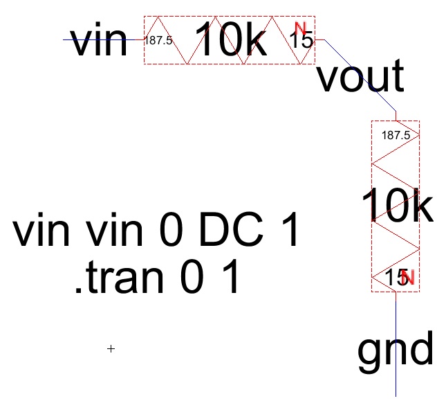
Figure 1.
Schematic view voltage divider with two 10k N-Well resistors.

Figure 2. LTSpice simulation for schematic voltage divider. Vout was indeed half of Vin.

Figure 3.
Layout view of voltage divider circuit with two 10k N-Well resistors.
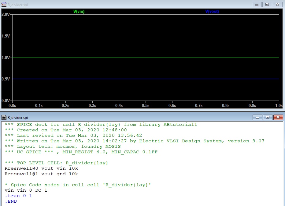
Figure 4. LTSpice simulation of the layout voltage divider. As you can see, Vout is half of Vin.
5. Discussion
The results from both the
schematic and layout circuits were as expected. The voltage output was
divided in half by both voltage dividers. The tutorial in this lab was
successful in teaching me how to create a simple circuit. There were
very little issues completing this lab, at one point the LTSpice
simulation would not open but worked fine once the ElectricVLSI
application was closed and opened again. The tutorial was very
informative and easily successful.