3. Materials and Methods:
Materials:
- Computer with LTSpice
- Breadboard
- 1k Ohm Resistor
- 100k Ohm Resistor
- 100pF Capacitor
- 680pF Capacitor
- Oscilloscope and 2 oscilloscope probes
- Function Generator
Methods:
The majority of this study was done simulating circuits on LTSpice using the symbols and components to build the circuit. Different components were chosen from the given component list and assembled on the new schematic space. Then the program was run using certain .tran conditions. Sections 1.3 and 2.1 were the only parts that were physically built on the breadboard. The function generator was set to square waves with certain specifications according to the lab. The oscilloscope had two probes that were set in the Vout and Vin positions to measure the time delay of the circuit. The various knobs on the oscilloscope were adjusted to compare the Vin and Vout waves.
4. Results:
1. Time Delay of Pulses:
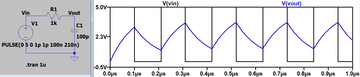
Figure 1. The Vout is oscillating throughout the Vin but not fully meeting the the input because the capacitor does not have enough time to charge fully.
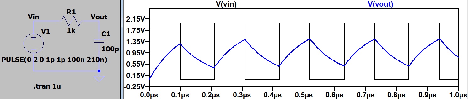
Figure 2. The same circuit with a lower Vin. The charge time does not depend on voltage so the same oscillating Vout outcome is shown.
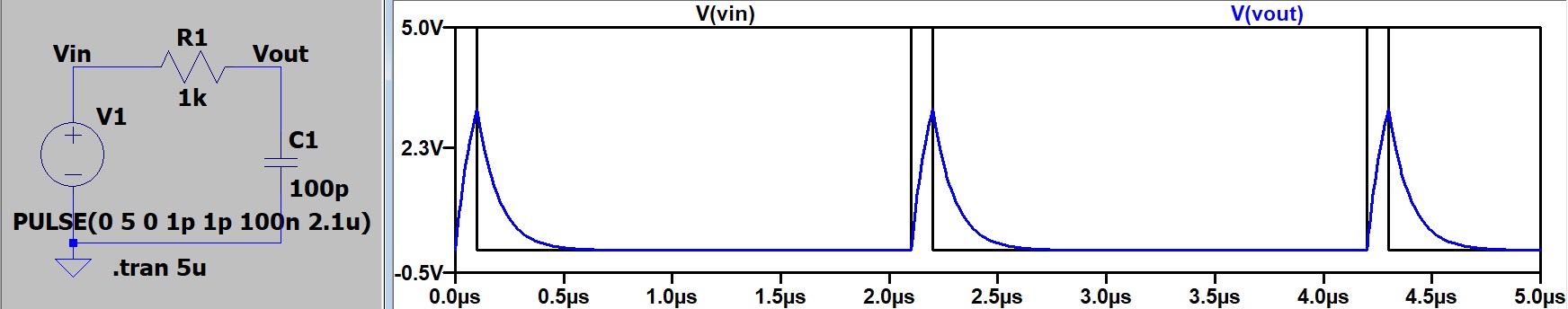
Figure 3. The circuit with the period changed. Nothing changes except the look of the graph.
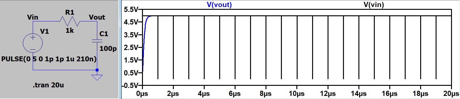
Figure 4. The circuit with the Ton changed. Again, nothing really changes except the look of the graph.
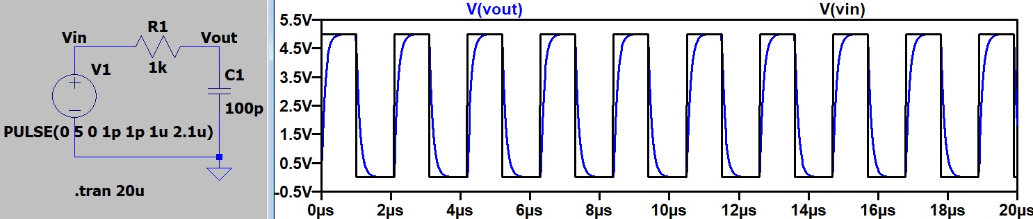
Figure 5. The circuit with both Ton and the period changed. This changes the time given for the capacitor to charge. Though it does fix the issue, the method is unrealistic.
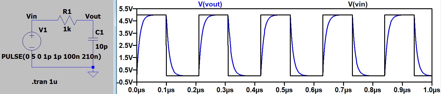
Figure 6. The original circuit with the 100pF capacitor replaced with a 10pF capacitor. It takes less time to charge this capacitor so Vout is able to reach the full 5V in time.
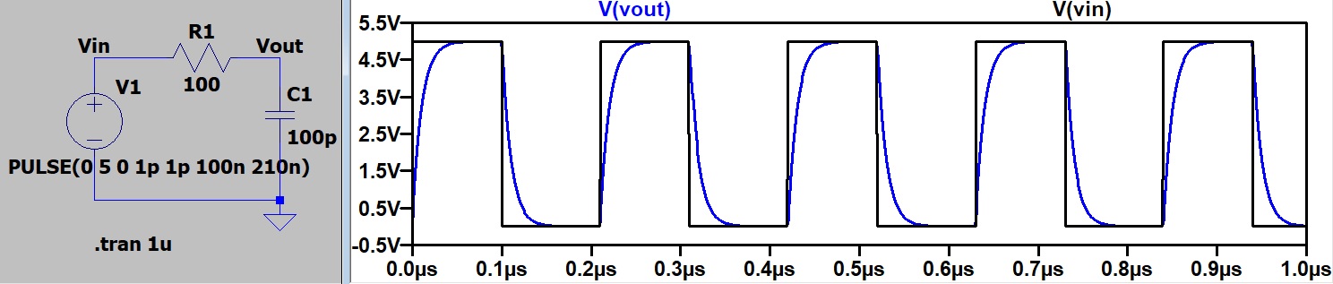
Figure 7. The original circuit with the 1k ohm resistor replaced with a 100 ohm resistor. The new resistors allows more flow and so the 100pF capacitor is able to charge in time.

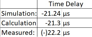
Figure 8. The measured time delay of the circuit from part 1.3
2. Time Delay and Amplitude Attenuation of Sinewaves
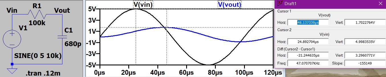
Figure 9. LTSpice simulation of the circuit from part 2
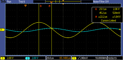
Figure 10. Oscilloscope measurement of the circuit.
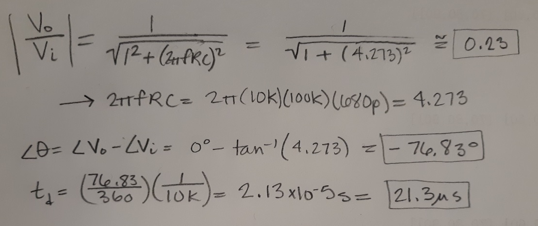
Figure 11. Time delay calculations