Part 1

Figure 1. Breadboard circuit from part 1
Table 1. Current and Voltage Data
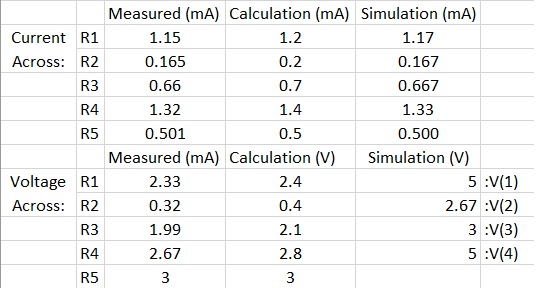
^^ I calculated and measured different voltages...
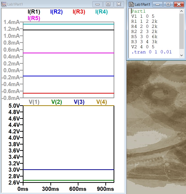
Figure 2. Simulation for part 1
Part 2:
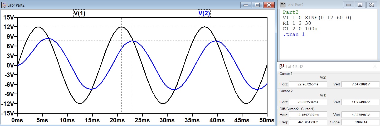
Figure 3. Simulation for part 2
Part 3:
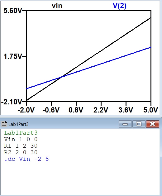
Figure 4. Part 3 simulation
Part 4:
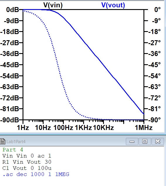
Figure 5. Part 4 simulation
Part 5:
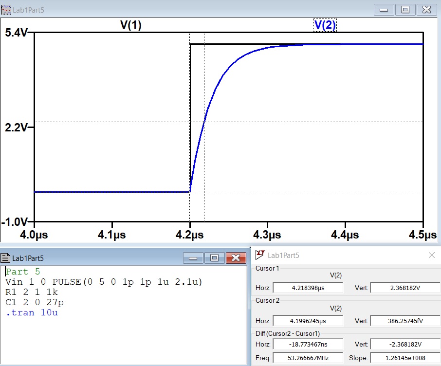
Figure 6. Part 5 simulation, time delay ~ 18.77
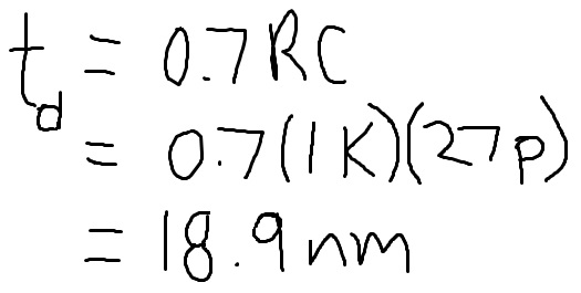
Figure 7. Part 5 time delay calculation
5. Discussion
The purpose of this lab was to review important methods learned in previous circuits classes. Part 1 was hands-on and helped brush up on testing and comparing separate forms of circuit analysis. The data in part 1 was very similar but not completely the same; the simulation and measured current was extraordinarily similar but the calculated was a little bit different. Variables like internal resistance and other factors due to real life may be the cause of this. One mistake made was the measurement of the voltages. The voltage across the resistor was calculated using Ohm's Law (V=IR) and measured by putting the multimeter in parallel with each resistor but the voltage of the nodes was presented in the simulation. Because I had done the calculation and measurements before the simulation I had not known that the voltage at the nodes what the measured voltage. Certain voltages can be matched up with V(1) can be compared to the voltage across R4 and V(3) is the same as R5 so it looks comparable. Other than my own human error, it can be said that LTSpice can be considered very accurate judging from this data. The LTSPice program is very impressive with its large range ofcircuit analysis capabilities.