Lab 5 Rectifiers and DC
Regulators
Outcome
of this lab:
1.
Be familiar with the Rectifiers and DC regulators.
2.
Be able to design a DC power supply. .
Instructions:
Task 1.
1.1 Build the following
circuit in LTSpice, report the diode 'built-in' potential.
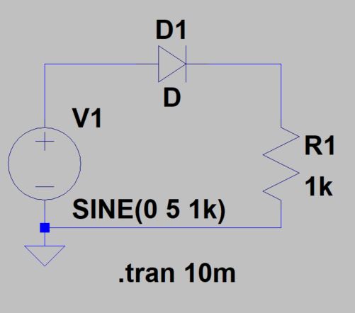
1.2 Modify the
built-in potential to 0.6 V. Show the input-output curves before and
after you change the built-in potential.
(hint: .model D
D(Vfwd=0.6))
1.3 Use a the
diode: 1N 5767
and a 1k resistor to build this circuit (can be 1.1 k or 1.2 k ohms) on
a breadboard. Use the oscilloscope to show the input and the output.
Report the
'built-in' potential of this diode.
Task 2
1.1 Build the
following circuit in LTSpice, report the input and output signal
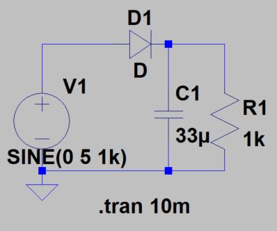
1.2 Build this
circuit on a breadboard and report the results.
Task 3
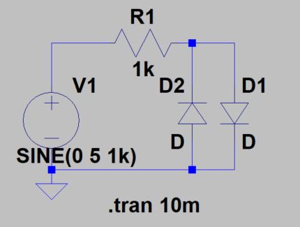
3.1 Build the
following circuit in LTSpice and on a breadboard. Explain the results
for credit.
3.2.
Build the following circuit in LTSpice (Note: only in LTSpice). Model
the Zener diode by this script: '.model D D(BV=10)', to define the
breakdown voltage to 10 V. The purpose of using zener diodes is to
protect your circuit. Whenever your input is suddenly larger than 10V,
the zener diodes will just breadown and 'Clamp' the voltage at 10 V.
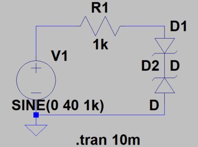
Use the Zener
diode 1n5230,
find the Vz of this diode in the datasheet and then verify on a
breadboard using the circuit above. Show the input and output on the
scope.
(You need to
pick up a proper Vpp for the sinewave to see the 'Clamping Circuit'
output).
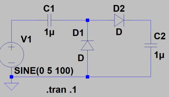
Task 4
Build the
following circuit in LTSpice and on a breadboard. Report the results
and explain why.
(This circuit is
called 'voltage doubler'. It can be used to provide a high-DC voltage).
-------------The end of the lab